1. Five decisions the calculator can support
| Conclusion | Evidence / boundary | Action |
|---|---|---|
| Reach is a geometric screen. | |L₁ − L₂| ≤ r ≤ L₁ + L₂; ideal unlimited joints. Modern Robotics §5.3 — Singularities | Check joint stops and collisions along the complete path. |
| Shoulder and elbow need separate load budgets. | J1 carries distal masses at longer lever arms; no universal J1/J2 torque ratio. Modern Robotics §8.1.3 — Understanding the Mass Matrix | Include elbow motor mass and tool center of mass. |
| A nonsingular pose can still be poorly conditioned. | Inspect κ(J), not just det(J). See the derived comparison below. Modern Robotics §5.3 — Singularities | Review joint velocity limits near boundaries. |
| A peak screen cannot establish a continuous rating. | Thermal demand requires the motion cycle and motor-drive limits. Kollmorgen — AKD2G motor thermal protection algorithm (KAS 3.05) | Supply a signed torque-time history and cooling conditions. |
| Low backlash is one part of tip precision. | Catalogs distinguish accuracy, lost motion and stiffness. Harmonic Drive — SHG-2UH-LW specification tables | Allocate an error budget, then validate on the assembled arm. |
2. When a 2-joint arm fits the task
A planar 2R mechanism (2 joints arm robot) controls two position coordinates. Tool orientation is coupled to its joint angles (θ₁ + θ₂). Assess whether a two-joint topology matches your process before comparing actuator quotations.
| Task | Candidate | Constraint / cost driver |
|---|---|---|
| Transfer in one fixed plane | 2R arm (2 joints arm robot) | Two actuators; tool orientation is not independently controlled. |
| Planar placement plus vertical insertion and yaw | 4-axis SCARA | Adds Z and rotation axes, drives and cable routing. |
| Independent spatial tool orientation | 6-axis articulated arm | More axes, integration and calibration work. |
| Large rectangular XYZ motion | Cartesian gantry | Frame footprint and linear-guide structure determine cost. |
| Fast repetitive 3D pick tasks | Delta architecture | Check actual payload, work envelope and trajectory against a vendor model. |
3. Reproduce the forward and inverse kinematics
θ₁ is measured counterclockwise from +X; θ₂ is the relative elbow angle. Link lengths are joint-center distances. The tool uses millimeters for geometry, converts to meters for loads, and reports joint angles in degrees.
x = L₁ cos θ₁ + L₂ cos(θ₁ + θ₂)
y = L₁ sin θ₁ + L₂ sin(θ₁ + θ₂)
c₂ = (x² + y² − L₁² − L₂²) / (2 L₁ L₂)
θ₂ = ±acos(c₂)
θ₁ = atan2(y, x) − atan2(L₂ sin θ₂, L₁ + L₂ cos θ₂)
The two signs produce the two IK branches. The solver first checks reach; it does not clamp an unreachable target into a fictitious solution. At equal-link folded origin, θ₁ is nonunique. With standard D–H convention, both rows have αᵢ = 0, dᵢ = 0, aᵢ = Lᵢ and the corresponding θᵢ.
Differentiating these position equations gives the task-specific Jacobian below. Rank loss removes a Cartesian velocity direction; it does not make every joint motion impossible. Background: Modern Robotics §5.3 — Singularities.
J = [ −L₁ sin θ₁ − L₂ sin(θ₁+θ₂)   −L₂ sin(θ₁+θ₂) ]
    [  L₁ cos θ₁ + L₂ cos(θ₁+θ₂)    L₂ cos(θ₁+θ₂) ]
det J = L₁ L₂ sin θ₂; v = J q̇4. Conditioning: maximum determinant is not isotropy
For the unweighted 2×2 position Jacobian above, κ = σmax/σmin. A local velocity circle requires κ = 1. Setting the two columns orthogonal and equal in length gives cos θ₂ = −L₂/L₁ and L₁² = 2L₂²: isotropy occurs at L₁/L₂ = √2 and θ₂ = ±135°. These are direct algebraic results for this model, not a universal optimum for an entire robot.
Equal links at 90° instead give κ ≈ 2.618. At fixed link ratio, the best condition occurs at cos θ₂ = −2r/(r² + 2), where r = L₁/L₂. The table is calculated from the same Jacobian used by the tool, assuming equal weighting of both joint rates.
| L₁/L₂ | |θ₂| at minimum κ | Minimum κ | Design implication |
|---|---|---|---|
| 1.000 | 131.810° | 1.618 | Equal reach does not produce isotropy. |
| 1.250 | 134.568° | 1.190 | Closer to an isotropic pose; still directional. |
| √2 ≈ 1.414 | 135.000° | 1.000 | Isotropic at this pose under this joint-rate metric. |
κ depends on the chosen task and joint weighting. Different motor speeds or an orientation task change that comparison. No fixed “95% reach” rule guarantees a feasible path: check velocities, acceleration, stops and clearance for the actual trajectory.
5. Torque model, assumptions and omitted loads
The tool assumes rigid uniform slender links, midpoint centers of mass, a point payload at the tip and a point elbow-actuator mass at J2. θ₁ = 0°, θ₂ = 0° places a vertical-plane arm horizontally to the right. The following magnitudes bound gravity over unrestricted postures, with g = 9.80665 m/s². Every mass is counted once.
G₁,max = g[m₁L₁/2 + mJ2 L₁ + m₂(L₁ + L₂/2) + mp(L₁ + L₂)]
G₂,max = g[m₂L₂/2 + mp L₂]

G₁(q) = g[(m₁L₁/2 + (mJ2 + m₂ + mp)L₁) cos θ₁
           + (m₂L₂/2 + mp L₂) cos(θ₁ + θ₂)]
G₂(q) = g(m₂L₂/2 + mp L₂) cos(θ₁ + θ₂)
In horizontal mode the gravity torque about the drive axes is zero. For acceleration, the rigid-body relation is τ = M(q)q̈ + C(q,q̇)q̇ + G(q), before friction and external loads. The screen includes coupling through M, using maximum absolute matrix entries and |q̈₁|, |q̈₂| ≤ α. The derivation is consistent with configuration-dependent inertia in Modern Robotics §8.1.3 — Understanding the Mass Matrix.
M₁₁,max = m₁L₁²/3 + mJ2 L₁²
          + m₂(L₁² + L₁L₂ + L₂²/3) + mp(L₁ + L₂)²
|M₁₂|max = m₂(L₂²/3 + L₁L₂/2) + mp(L₂² + L₁L₂)
M₂₂ = (m₂/3 + mp)L₂²
A₁ = (M₁₁,max + |M₁₂|max) α
A₂ = (|M₁₂|max + M₂₂) α
Planning screenᵢ = (Gᵢ,max + Aᵢ) × editable multiplier
In high-speed motions, the velocity-dependent Coriolis and centrifugal vector C(q, q̇)q̇ generates significant coupling. For this 2-joint planar serial arm with uniform slender links and point masses:
h = (m₂ L₂/2 + mp L₂) L₁ sin θ₂
C(q, q̇)q̇ = [ -h(2q̇₁q̇₂ + q̇₂²) ]
             [       h q̇₁²       ]
Notice that even when the elbow is held stationary (q̇₂ = 0), a fast shoulder swing (q̇₁) produces a centrifugal reaction torque τ₂ = h q̇₁² forcing the elbow outward. The J2 actuator must actively provide sufficient holding and braking torque to maintain path fidelity.
The bounds need not occur at the target pose. This is a conservative bound for the included gravity and acceleration terms, not for the complete machine. It excludes velocity terms, motor and reducer inertia, friction, efficiency losses, off-center tools, contact forces and stop shocks. The default ×1.5 is a planning assumption with no safety certification.
A useful sensitivity check: adding 0.1 kg at J2 with L₁ = 0.3 m adds 0.2942 Nm to maximum vertical gravity torque and 0.009 kg·m² to shoulder inertia. It adds no payload lever arm about J2. These are Δτ = Δm·g·L₁ and ΔI = Δm·L₁², not a universal mass-penalty percentage.
6. Continuous torque, regeneration and missing inputs
A single acceleration value cannot determine RMS duty torque or braking energy. For known piecewise signed torques at a consistent shaft, τrms = √(Στᵢ²tᵢ / Σtᵢ). Regenerative torque remains squared: a −10 Nm deceleration contributes the same heating proxy as +10 Nm for equal time. A fixed peak/2.2 rule or clipping negative torque to zero would understate some duties.
| Quantity | Tool status | Required evidence / next step |
|---|---|---|
| Static and acceleration screens | Calculated under explicit rigid-link assumptions | Verify measured COMs and include all attached masses. |
| Continuous thermal rating | Not determined | Signed torque-time trace, speed, ambient, enclosure, cooling and motor-drive thermal limits. |
| Braking energy and shunt resistor | Not determined | Use E = ½q̇ᵀM(q)q̇ plus potential-energy change; assess simultaneous axes, bus limits and pulse power. |
| Gear ratio and voltage | Not validated | Torque-speed curves, efficiency, rotor inertia, drive limits and supply behavior. |
| Bearing life and overturning moment | Not determined | Resolve radial, axial and bending loads from the actual 3D mounting geometry. |
Review drive and motor thermal capacity separately; there is no universal 40–60°C derating table for all actuators. Manufacturer guidance: Kollmorgen — AKD2G motor thermal protection algorithm (KAS 3.05). A motor brake is also not automatically suitable for repeated dynamic stops.
Dynamic trajectory tracking also requires matching the reflected load inertia to the motor rotor inertia: J_reflected = J_arm(q) / N², where N is the motor-to-output speed ratio for an ideal reducer and J_arm is the effective output inertia for the motion considered. Add gearbox input inertia and account for the changing mass matrix and coupled joint motion. There is no universal 5:1, 10:1 or 20:1 pass/fail threshold: mechanics, drive tuning and the required bandwidth determine acceptable response. Nidec Drives — Sizing a motor & drive system (May 2, 2018) explains the risk of sizing by fixed ratios. Validate settling and stability on the candidate system.
7. Compare actuator technologies using the same requirements
| Technology | Reason to investigate | Verify before choosing |
|---|---|---|
| Strain-wave geared joint | Compact reduction with manufacturer-described zero backlash; compliance and lost motion still need checking. The Harmonic Drive — CSG-GH / CSF-GH gearhead comparison advertises 30% higher torque and 42% longer life for CSG-GH versus CSF-GH only. These are manufacturer family comparisons, not RJA specifications or complete-arm accuracy guarantees. | Lost motion, compliance, repeated peak, life, efficiency and output bearing capacity. |
| Cycloidal geared joint | Investigate model-specific shock capacity and torsional stiffness for reversing duty. A momentary limit is not an allowable repeated-cycle torque. | Exact model/ratio torque and stop limits, moment load, mass and duty. |
| Precision planetary joint | Investigate available ratios, efficiency and system cost. | Backlash class under reversal, stiffness, integration and the tip-error budget. |
| Direct drive | Eliminates reducer backlash and gear wear mechanisms. | Motor torque and thermal envelope, bearing system, cogging, encoder and control quality. |
Compare integrated harmonic joints, cycloidal joint actuators and planetary joint modules against the same motion profile. Request model datasheets and CAD interface drawings for shortlisted candidates.
Review your actuator shortlist with engineeringHarmonic Drive — Strain-wave technology describes the gearing principle. The Harmonic Drive — SHG-2UH-LW specification tables and Nabtesco — Precision reduction gear product guide (PDF) show why rated, repeated-peak and momentary limits must be treated separately. A manufacturer’s gearbox rating does not establish the motor, drive or complete joint rating.
There is no supported payload threshold that automatically requires cycloidal or strain-wave gearing. Derive the output-speed range, load history and stiffness target, then request comparable candidates with the same duty and mounting assumptions. Compare total integration cost: drive, encoder, brake, bearings, cabling, cooling and validation, as well as unit price.
8. Precision, bearings and internal cable routing
For small angular errors, an upper estimate is δtip ≤ (L₁ + L₂)|δθ₁| + L₂|δθ₂| with angles in radians. At a 0.6 m lever arm, a 3 arcmin angular change gives approximately 0.524 mm arc displacement. That is a geometric contribution, not a measured ± repeatability specification. Add structural compliance, alignment, encoder and calibration errors.
Separate drive-axis torque from bending moment about perpendicular axes. Resolve the bearing loads in 3D. Crossed-roller and paired angular-contact designs must be compared at the actual diameter, spacing, preload and mounting stiffness; no universal 3× stiffness multiplier is justified. THK — Cross-roller ring nominal life and combined loads explains combined loads and notes limitations for oscillating motion and lubrication.
Pc = X · (Fr + 2 M / Dpw) + Y · Fa
L₁₀ = 10⁶ · (C / Pc)^(10/3)  [revolutions; nominal conditions]
Lh = L₁₀ / (60 n)  [hours; continuous rotary motion]
ΔZ_tilt ≈ (M_tilt / K_θ) · (L₁ + L₂)  [fully extended, small angle]
In the THK nominal-life model, C, Pc, Fr and Fa are in N; use M in N·mm and Dpw in mm. Select X and Y from the catalog’s load-ratio cases; X multiplies both Fr and the moment term. The 10/3 roller-life exponent and 90% survival definition concern rolling fatigue, not a guaranteed service interval. Temperature, shock, preload and lubrication require the supplier’s modified life assessment. The rotary-speed conversion uses n in rpm; oscillating robot joints need an oscillatory-motion assessment. THK — Cross-roller ring nominal life and combined loads
For the illustrative base-tilt estimate, use K_θ in Nm/rad and lengths in meters to obtain ΔZ in meters; 1 kNm/rad = 1 Nm/mrad. A 60 Nm moment with K_θ = 120 Nm/mrad gives 0.5 mrad tilt and 0.30 mm tip droop at 600 mm reach. This accounts only for base tilt at full extension; add elbow, link and mounting compliance. It predicts static deflection, not repeatability. THK — Cross-roller ring moment rigidity explains the mounting limits. Use the full ISO 9283:1998 — Manipulating industrial robots: Performance criteria protocol for a repeatability claim; the calculator does not certify compliance.
| Interface | Unknown in this calculator | Minimum validation |
|---|---|---|
| Output bearing | Radial/axial loads, bending moments and mounting compliance | Free-body diagram, catalog combined-load check, housing and fastener review. |
| Hollow shaft | Connector passage, bundle clearance, bend and torsion | Route the actual bundle through CAD and test across both joint ranges. |
| Seals and enclosure | Ingress, grease compatibility, internal heat | Specify assembly-level environment requirements and test the enclosure. |
| Tip precision | Loaded error, drift and reversal behavior | Measure the task’s load, approach direction, warm-up and temperature conditions. |
Internal routing can reduce exposed loops but still twists and bends the cable. Neither bore size nor routing method establishes millions of cycles, cleanroom suitability or an ingress rating without assembly test evidence.
9. Risks, alternatives and release checks
| Risk | Failure mechanism | Mitigation / alternative |
|---|---|---|
| Misuse: singular path | A reachable endpoint hides infeasible velocity demands near a rank loss. | Inspect κ and joint speeds along the path; reroute, slow down or use a suitable singularity-aware controller. |
| Misuse: unsupported vertical load | Power loss can allow a gravity-loaded arm to fall. | Perform a risk assessment and validate appropriate support/braking; a torque screen does not establish safety. |
| Reliability: overheating or overload | An adequate short peak rating hides holding duty or repeated-stop stress. | Evaluate thermal duty and each mechanical load class; reduce acceleration or add counterbalance if appropriate. |
| Cost: overselecting from peak alone | Large hardware increases elbow mass, upstream load and integration cost. | Compare a motion redesign, lower distal mass and multiple documented candidates. |
| Scene mismatch: spatial orientation | Two axes cannot independently satisfy a spatial tool pose. | Change fixturing or choose an architecture with enough axes. |
For industrial robot safety, consult ISO 10218-1:2025 — Industrial robot safety and Part 2 for application and cell integration. Applicable requirements depend on the robot and application. This calculator supplies no conformity assessment, safety function validation or guarantee of safe human collaboration.
10. Four reproducible design examples
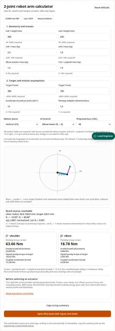
These are illustrative calculations, not customer installations or measured product performance. Each starts from the stated link masses, elbow mass and payload, uses the displayed α bound at both joints and multiplier 1.5. Enter the same values in the tool to reproduce the results; no cycle time, noise, repeatability or lifetime is inferred.
| Scenario and assumptions | Calculation: gravity J1 / J2 | Result: screen J1 / J2 | Next decision |
|---|---|---|---|
| SCARA sorting concept L₁/L₂ 320/280 · m₁/m₂ 2.2/1.5 · mJ2/mp 1.1/1; α 30; horizontal | 0.00 / 0.00 | 51.72 / 17.64 | Gravity-axis torque is zero; assess dynamic duty and bearing bending separately. |
| Vertical laboratory concept L₁/L₂ 200/180 · m₁/m₂ 1.2/0.9 · mJ2/mp 0.7/0.4; α 10; vertical | 6.60 / 1.50 | 13.40 / 3.39 | Add holding dwell, tool COM and contamination requirements before selecting hardware. |
| Heavy vertical concept L₁/L₂ 450/400 · m₁/m₂ 7/5.2 · mJ2/mp 3.2/5; α 8; vertical | 104.39 / 29.81 | 269.92 / 86.99 | Evaluate both joints and stop loads; payload alone does not establish a reducer type. |
| Vertical static-only check L₁/L₂ 300/250 · m₁/m₂ 2.5/1.8 · mJ2/mp 1.2/1.5; α 0; vertical | 22.80 / 5.88 | 34.20 / 8.83 | This isolates gravity. Continuous holding capability and safe power-off support remain separate checks. |
11. Engineering FAQ
Geometry and control
What is a 2 joints arm robot, and when is a two-joint planar architecture preferred?
A 2 joints arm robot (also referred to as a two-joint robot arm, 2-DOF planar manipulator, or 2R arm) connects two revolute joints in series to position an end-effector within a 2D planar annulus. Unlike 6-axis spatial arms that position (X, Y, Z) and orient (roll, pitch, yaw) independently, a 2 joints arm robot controls planar tip coordinates while orientation remains coupled to θ₁ + θ₂. A two-joint arm can suit fixed-plane transfer, inspection and sorting when independent tool orientation and vertical travel are unnecessary. Fewer axes can reduce integration work, but both joints still contribute backlash and compliance. Stiffness, payload and total cost depend on the chosen hardware; insertion or independent yaw generally requires additional axes.
What can a 2-joint robot arm control?
Two revolute joints can position a tool in a plane within an ideal annulus. Tool orientation follows θ₁ + θ₂ and cannot generally be specified independently. Add axes if the task needs independent orientation or out-of-plane motion.
Does reachable mean collision-free?
No. The calculator checks only ideal link geometry. Mechanical joint stops, self-collisions, fixtures, cable bend limits and tool clearance can all remove regions from that annulus. Verify the entire trajectory in the real mechanism.
Why are there two inverse-kinematics branches?
Most interior target points have positive and negative θ₂ solutions. Choose the branch that respects joint and collision limits. Switching branches during a move requires path planning rather than an abrupt command change.
What happens when equal links fold to the origin?
Infinitely many shoulder angles place the tip at the origin when θ₂ is ±180°. The tool reports a nonunique singular pose and suppresses target-specific angles and gravity torques.
Is maximum manipulability the same as isotropy?
No. Normalized |sin θ₂| is maximized at 90°. Isotropy requires equal singular values of the position Jacobian. For unweighted joint rates this occurs at L₁/L₂ = √2 and |θ₂| = 135°.
How do centrifugal and Coriolis cross-coupling torques affect actuator sizing in a 2 joints arm robot?
In a serial two-joint planar arm, moving joint 1 creates a centrifugal reaction torque on joint 2 equal to τ₂ = h · q̇₁², where h = (m₂·L₂/2 + mp·L₂)·L₁·sin(θ₂). Even if joint 2 is commanded to maintain zero velocity (q̇₂ = 0), high-speed shoulder rotation exerts a strong outward flinging torque on the elbow. The elbow actuator and servo drive must actively generate restraining torque to hold position, or risk losing track or experiencing excessive following error.
Loads and actuator sizing
Are these torque screens ready for ordering?
No. They combine an all-posture gravity bound and a coupled rigid-link acceleration bound with an editable planning multiplier. Velocity-dependent loads, friction, reflected rotor inertia, process forces and stops still require calculation.
What reflected load inertia ratio (J_load / J_motor) should a 2 joints arm robot target?
In precision robotics, load inertia reflects back to the motor shaft divided by the gear ratio squared: J_reflected = J_arm(q) / N². There is no universal acceptable ratio or mandatory detuning threshold. Include gearbox input inertia and configuration-dependent joint coupling, then compare the chosen motor-drive guidance and validate bandwidth, stability and settling over the trajectory. Section 6 links manufacturer sizing guidance on the limits of fixed ratio rules.
Does horizontal mode remove all gravity loads?
It removes gravity torque about the ideal vertical joint axes in a horizontal XY arm. The structure, bearings and base still support weight and bending moments.
Why is there no automatic continuous torque recommendation?
Continuous thermal demand depends on signed torque over time, duty, speed, cooling, ambient and the motor-drive combination. Dividing an estimated peak by a fixed number cannot establish a continuous rating.
Can I calculate RMS torque manually?
Yes. For known piecewise-constant signed torques, square each torque, weight by its duration, sum, divide by total cycle duration, then take the square root. Include holding intervals. Compare at a consistent shaft and verify thermal conditions.
What planning multiplier should I use?
The default 1.5 is a transparent page assumption, not a standard or a guarantee. Define load uncertainty and each candidate’s repeated-peak, stop, thermal and fatigue limits. A multiplier cannot replace missing load cases.
Can the tool select a gear ratio or bus voltage?
No. It records a proposed bus voltage for discussion. Gear ratio requires output speed, motor torque-speed data, reflected inertia, efficiency and duty checks. Confirm insulation, drive and power supply compatibility separately.
Mechanics and validation
Is a strain-wave reducer mandatory for sub-millimeter positioning?
No single reducer technology guarantees a tip-error target. Build an error budget for backlash, lost motion, compliance, encoder accuracy, calibration and link deflection. Compare candidates against that budget.
Does a hollow bore guarantee long cable life or IP sealing?
No. Check bundle size, connectors, bend radius, torsion, strain relief and seals for the actual motion. Test the assembled routing; a bore diameter alone supplies no cycle-life or ingress rating.
Can the gravity torque be used as bearing overturning moment?
Not directly. Drive-axis torque and bending about perpendicular axes are different load components. Resolve a 3D free-body diagram at each bearing, including tool and mounting offsets.
How does crossed roller bearing moment stiffness affect TCP droop in a horizontal 2 joints arm robot?
In a horizontal planar arm, all gravitational weight acts perpendicular to the joint rotation axes, producing a cantilever tilting moment M_tilt on the base joint bearing flange. Under bearing angular moment stiffness K_θ (measured in kNm/rad or Nm/mrad), the inner ring tilts by Δθ_tilt = M_tilt / K_θ. Across the extended arm radius (L₁ + L₂), this causes a vertical TCP droop of ΔZ = Δθ_tilt · (L₁ + L₂). For example, a 60 Nm moment acting on a bearing with K_θ = 120 Nm/mrad causes 0.5 mrad tilt, which drops the tip by 0.30 mm over a 600 mm reach.
How is pose repeatability verified under ISO 9283 for a 2 joints arm robot?
Use ISO 9283:1998 performance criteria and the full applicable test method. Record the load, commanded poses, approach direction, speed, warm-up, environment and measuring system. Repeated same-direction approaches characterize scatter; they do not establish absolute accuracy. A mean-plus-three-standard-deviations statistic is not automatically a 99.73% confidence guarantee. The public ISO record linked in Sources confirms the standard, not a complete compliant protocol; no hardware repeatability is measured here.
Are the scenarios on this page measured customer results?
No. They are reproducible calculations using stated illustrative dimensions and masses. Repeatability, cycle time, cleanroom suitability, noise and service life are unmeasured here.
What should I send for engineering review?
Copy the inputs and limits, then add a joint trajectory, tool center of mass, forces, cycle duration, ambient and mounting geometry. Ask for candidate datasheets, CAD, thermal validation and test evidence.
12. Sources, review date and evidence limits
Published November 1, 2026. By Robot Joint Actuator. Reviewed . Sources below support the stated principles or provide model-specific examples. The kinematics, conditioning and load equations are derived here for the declared ideal model. Public catalog summaries do not verify a complete machine or replace the full applicable standard.
- Modern Robotics §5.3 — Singularities
Jacobian rank and lost velocity directions. The 2×2 equations below are derived for this page’s planar model.
- Modern Robotics §8.1.3 — Understanding the Mass Matrix
Configuration-dependent inertia and joint coupling; basis for the rigid-link screening derivation.
- Harmonic Drive — Strain-wave technology
Manufacturer description of strain-wave engagement and zero backlash; not proof of complete-arm accuracy.
- Harmonic Drive — SHG-2UH-LW specification tables
Separately lists rated torque, repeated peak, momentary peak, accuracy, mass and stiffness. These are external manufacturer examples, not RJA product specifications.
- Nabtesco — Precision reduction gear product guide (PDF)
Model-specific torque, output speed and moment limits. Compare exact model and ratio; no universal overload percentage is assumed here.
- THK — Cross-roller ring nominal life and combined loads
Combined radial, axial and moment load assessment; lubrication and oscillating-motion limitations.
- ISO 9283:1998 — Manipulating industrial robots: Performance criteria
Edition 2, published April 1998; official record confirms the standard’s identity and status. The public summary does not specify the complete test protocol; consult the full standard for a compliant repeatability test.
- Harmonic Drive — CSG-GH / CSF-GH gearhead comparison
Manufacturer advertises 30% higher torque and 42% longer life for CSG-GH versus CSF-GH. This family comparison does not establish every torque category, complete-joint performance or RJA ratings.
- Nidec Drives — Sizing a motor & drive system (May 2, 2018)
Explains why fixed inertia-ratio rules can oversize a motor; speed, torque, mechanics and the application response must be assessed together.
- THK — Cross-roller ring moment rigidity
Bearing-only stiffness curves do not include housing, flange and bolt deformation. The tip-droop example below is an illustrative small-angle calculation.
- Kollmorgen — AKD2G motor thermal protection algorithm (KAS 3.05)
Versioned manufacturer documentation describes peak/continuous motor current, the coil thermal constant and thresholds shared with drive protection. Consult the selected motor/drive documentation; no universal ambient derating curve is inferred.
- ISO 10218-1:2025 — Industrial robot safety
Edition 3, published February 2025. Robot safety scope; application and cell integration are addressed by Part 2. Consult the full applicable standards and a risk assessment.
| Parameter / Load Case | Status | Why It Cannot Be Inferred | Minimum Required Proof |
|---|---|---|---|
| Flexspline shock fatigue life under repetitive E-stop events | No reliable public data yet | No stop trajectory or model-specific shock-cycle data is supplied. Stop torque and fatigue depend on inertia, speed, stopping time, compliance and the chosen reducer; nominal catalog life alone does not validate repeated emergency stops. | Calculated stop load history and manufacturer-approved momentary limits, allowed stop cycles and fatigue validation for the selected model. |
| Sealed arm link internal temperature equilibrium | Pending confirmation | Heat dissipation in enclosed unventilated tubular arm links depends heavily on link surface area, wall thickness, ambient airflow convection, and joint conduction paths. | Thermal mock-up test data under 100% duty cycle at target maximum ambient operating temperature. |
| Dynamic TCP residual settling oscillation time | Pending confirmation | Settling depends on controller tuning, inertia, structural modes, cable forces and transmission compliance. Their relative contributions have not been measured for this concept. | Assembled arm laser interferometer or high-speed visual position settling record following a maximum-speed step move. |
| Universal overload safety margins across diverse gear suppliers | No reliable public data yet | Manufacturers specify rated, repeated-peak and momentary torque separately for each model, ratio and duty. These limits cannot be inferred from a universal multiplier. | Vendor-signed specification sheet detailing allowable shock cycles and peak overload torque limits. |
Evidence still required: selected actuator datasheets, actual duty and thermal measurements, system repeatability, bearing load geometry, cable life, ingress protection and cleanroom test results. These are explicitly unknown; the page makes no measured claims for RJA models.