Dual-Encoder Architecture in Robot Joint Actuators: Resolving Transmission Error, Deflection, and End-Effector Drift
Compare dual-encoder robot joint actuators, accuracy limits, tuning risks, and acceptance tests. Use the RFQ checklist to scope your next supplier quote.
Engineering review: October 27, 2026. This guide is for robot OEM engineers and procurement teams evaluating dual-encoder robot joint actuators globally. It covers motor-side plus output-side position feedback; it does not establish medical suitability, a safety rating, or guaranteed tool center point (TCP) accuracy.
The numerical examples below are reproducible engineering and cost calculations using stated assumptions, not physical test results, customer cases, or supplier quotations. For a sourcing decision, start with the supplier acceptance checklist.
Key Takeaways
- Resolution is not accuracy: A 19-bit motor encoder resolves 524,288 positions per motor revolution. Dividing its reading by the gear ratio does not directly measure gearbox deflection, lost motion, or output angle.
- Size the error budget first: In the worked example below, 50 Nm acting on an assumed output stiffness of 100,000 Nm/rad produces about 0.425 mm of tangential displacement at an 850 mm lever arm. This is an illustrative single-joint calculation, not a typical robot specification.
- Use two feedback locations: Motor feedback supports commutation and velocity control; an output encoder measures the flange relative to the housing. Output feedback can reduce transmission-related position error within the controller's bandwidth and torque limits.
- Quote the complete integration: Compare the encoder, mounting, wiring, calibration, firmware, and validation costs rather than assuming a universal per-axis premium.
- Validate the complete mechanism: Dual-loop tuning must account for compliance, resonance, latency, and payload changes. Neither two encoders nor a high bit count guarantees TCP accuracy or safety-rated collision detection.
1. The Core Engineering Problem: Why Motor-Side Encoders Fall Short Under Load
In early-stage robotics development, engineering teams frequently select joint actuators based purely on the headline resolution listed on the motor datasheet. When a vendor advertises a 17-bit, 19-bit, or even 21-bit optical encoder integrated into a frameless brushless DC (BLDC) motor, it is tempting to calculate theoretical output resolution by simply multiplying the encoder counts by the gear reduction ratio:
Ideal counts per output revolution = 2^bits × NFor a 19-bit motor encoder paired with a 100:1 strain wave gearhead:
524,288 × 100 = 52,428,800 counts/output revolution
360° / 52,428,800 ≈ 0.00000687° per count
This ideal quantization step assumes a known ratio and correct motor-turn tracking. It is not an output accuracy specification: encoder scale error, mounting error, transmission error, and compliance remain. Evaluate absolute accuracy, repeatability, and dynamic tracking separately under the intended payload and temperature conditions.
The Mechanics of Transmission Error
The fundamental limitation of relying solely on a motor-side encoder is that the motor shaft does not connect rigidly to the robot link. Between the motor rotor and the output flange is a mechanical speed reducer, such as a strain wave (harmonic) gear set or a precision cycloidal (RV) drive.
No mechanical transmission is infinitely stiff or geometrically perfect. A useful error-budget model relates physical output angle to motor angle and reduction ratio N:
theta_load = theta_motor / N + e_kinematic + e_torsion + e_lost_motion + e_thermal- Kinematic transmission error: Gear geometry, eccentricity, and assembly errors create cyclic deviations. Their amplitude and harmonic content depend on the reducer and installation; request the specific error map rather than assuming a universal arcminute range.
- Torsional wind-up: For a locally linear spring approximation,
e_torsion = T_load / K_t, whereK_tis output-referenced stiffness in Nm/rad. Real stiffness and hysteresis depend on torque, direction, temperature, and reducer design; a single stiffness value may not cover the full operating range. - Backlash and lost motion: Geometric clearance and elastic hysteresis are distinct. A "zero-backlash" label does not establish zero reversal error. Require the supplier's loading and reversal test conditions.
- Thermal effects: Differential expansion, bearing preload changes, and mounting distortion can alter the output angle or the sensor reference. Output feedback cannot correct thermal distortion beyond its measurement location.
A motor-side encoder does not directly observe these output error terms. Model-based estimation can help, but it requires validation and is different from measuring the output flange. The terms above are an error-budget decomposition, not a claim that all effects are independent or additive under every operating condition.
Worked Example: Translate Joint Deflection into a TCP Budget
Assume one joint has T_load = 50 Nm, local stiffness K_t = 100,000 Nm/rad, and a rigid perpendicular lever arm L = 0.85 m. Using the small-angle approximation:
Angular deflection = 50 / 100,000 = 0.0005 rad ≈ 1.72 arcmin
Tangential displacement ≈ L × angular deflection
                         = 0.85 × 0.0005 = 0.000425 m = 0.425 mm
If that joint's allocated tangential error is 0.10 mm at 850 mm, its angular budget is 0.10 / 850 ≈ 0.000118 rad, or about 24.3 arcseconds. A 19-bit output encoder has a 2.47 arcsecond count spacing, but its installed accuracy must still fit the budget alongside residual tracking error and other joint errors. For multiple axes, use the robot Jacobian and actual posture; link bending, base motion, tooling, and calibration errors need separate allocations.
2. Architectural Blueprint: Dual-Encoder Joint Layout & Signal Path
A dual-encoder architecture adds direct output feedback to motor feedback. HEIDENHAIN’s robotics overview describes downstream secondary encoders and the KCI 120 Dplus as ways to compensate transmission-related deviations. That supports the architecture, not a universal residual-error guarantee.
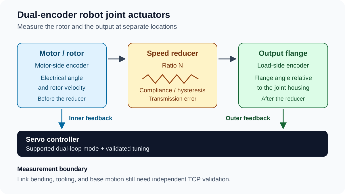
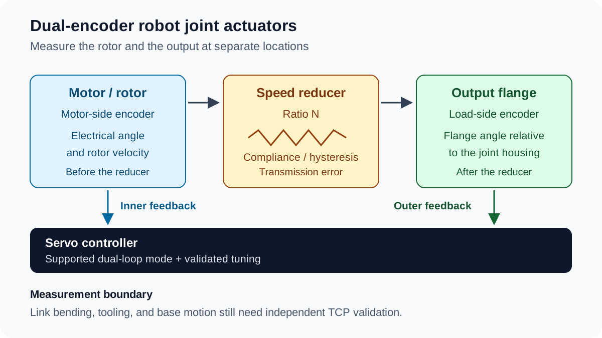
Conceptual signal path, not a product cross-section. The output encoder measures the flange relative to the housing; it does not observe bending further along the arm.
Function Division Across the Two Encoders
- Primary Motor-Side Encoder (Commutation & Velocity):
- Position in Assembly: Mounted on the rotor before the gear input.
- Primary Duty: Provides rotor angle for field-oriented control (FOC) and velocity feedback for the inner control loop.
- Why Output Feedback Alone Is Insufficient: Reducer compliance, lost motion, and the ratio complicate inference of rotor electrical angle. A geared output encoder alone is generally unsuitable for direct commutation. Other rotor-sensing or sensorless observer approaches exist, but need their own operating-range and startup validation.
- Secondary Load-Side Encoder (Kinematic Position):
- Position in Assembly: References the rotating output flange to the stationary joint housing, downstream of the reducer. The exact bearing and sensor stack depends on the module.
- Primary Duty: Measures local flange angle for an outer position loop; a stable controller can adjust motor motion to reduce measured output error.
- Communication Interface: BiSS-C, SSI, EnDat, or another interface must match the actual drive. Single-turn versus multi-turn behavior is a separate product feature.
- Control Responsibility: Correction is limited by sensor accuracy, latency, torque headroom, and mechanical bandwidth. Joint position feedback cannot measure downstream link or tool deflection.
Two measurement locations do not by themselves constitute independent safety channels. Also distinguish serial clock rate, feedback update rate, and closed-loop bandwidth: none establishes the others.
3. Structural Comparison: Single-Encoder vs. Dual-Encoder Actuators
For procurement directors, systems integrators, and mechanical lead engineers, selecting between single-encoder and dual-encoder configurations requires balancing initial unit BOM cost against end-effector accuracy, safety, and field reliability.
The table below compares seven engineering and procurement dimensions. Outcomes depend on the complete sensor, drive, and mechanism implementation.
| Comparison Dimension | Single Motor-Side Encoder | Motor + Output Encoder | Engineering & Procurement Impact |
|---|---|---|---|
| Motor Commutation (FOC) | Uses rotor feedback | Usually retains rotor feedback | Specify the actual rotor-angle source and startup behavior; two encoders do not require a particular sensing technology. |
| Output Position Accuracy | Output inferred through reducer ratio | Output measured locally and corrected within control limits | Request installed output accuracy under stated torque and temperature; do not substitute bit count or a universal arcminute figure. |
| Torsional Deflection | Requires a validated compliance model to estimate output error | Difference between aligned motor and output readings reveals relative displacement | Account for scale error, ratio, offsets, and synchronized sampling before interpreting the difference. |
| External Torque Estimation | Often inferred from motor current and a friction model | Relative displacement can inform a calibrated stiffness model | Neither method automatically replaces a wrist force/torque sensor or establishes a safety-rated collision function. |
| BOM & Integration Cost | Baseline motor feedback integration | Adds sensor, mounting, electronics, firmware, and validation | Obtain itemized quotations at the same volume, calibration scope, and acceptance criteria. |
| Wiring & Harnessing | One feedback path | Separate feedback paths or supported multi-device topology | BiSS supports daisy chaining, but both encoders and the master must support the selected arrangement. |
| Production Calibration | Rotor alignment and applicable output checks | Adds output zero, installed error, and channel alignment checks | Agree test uncertainty, temperature, traceability, and whether a correction map is required. |
4. Secondary Load-Side Encoder Technologies: Optical vs. Magnetic vs. Inductive
When specifying a secondary load-side encoder for a hollow-shaft robot joint actuator, procurement and mechanical engineering teams can compare magnetic, optical, and inductive sensing technologies.
A hollow bore can favor modular ring or disk encoders that leave room for cables and hoses. Enclosed hollow-shaft products may also be suitable; packaging should follow the actual bore and bearing stack. Novanta’s product finder lists optical and inductive options and interface variants. Its portfolio is not evidence that every product meets one common accuracy or installation tolerance.
The table is a sourcing framework, not a measured ranking of all three technologies. Compare specific part numbers at the required diameter and temperature.
| Technical Metric | Magnetic Ring Encoder | Optical Disk / Scale | Inductive Encoder |
|---|---|---|---|
| Resolution | Request absolute position-word bits and effective noise | Separate scale graduation, interpolation, and position-word bits | Request position-word bits and effective noise |
| Installed Accuracy | Check magnetization, eccentricity, and field sensitivity | Check scale accuracy, mounting error, and interpolation error | Check target geometry, mounting error, and calibration |
| Hollow Bore | Verify ring ID, OD, and readhead clearance | Verify scale width and readhead clearance | Verify PCB/target dimensions and clearance |
| Contamination | Non-optical sensing can tolerate contamination; sealing still matters | Assess grease film, dust, and condensation against the enclosure design | Non-optical sensing can tolerate contamination; verify the rated environment |
| Magnetic / EMC Exposure | Verify stray-field tolerance near the motor and brake | Verify electronic EMC and cable routing | Verify product-specific magnetic-field and EMC limits |
| Alignment / Axial Space | Use the selected product's air-gap, runout, and stack requirements | Use the selected product's gap, tilt, and runout requirements | Use the selected product's target-gap and mounting requirements |
| Cost & Calibration | Quote the installed and calibrated assembly | Quote the installed and calibrated assembly | Quote the installed and calibrated assembly |
Engineering Guidance for Sourcing
- When to Choose Optical: Shortlist optical products when the required installed accuracy is supported by the scale and calibration data, and the cavity can remain within the specified contamination limits. Technology alone does not qualify a surgical or metrology application.
- When to Choose Magnetic: Consider magnetic products when their measured accuracy meets the budget and the housing can meet the stated stray-field, temperature, and sealing limits. Test with motor and brake energized.
- When to Choose Inductive: Consider inductive products for suitable packaging and environmental performance. HEIDENHAIN describes inductive robotic motor encoders and a combined motor/output device; verify the chosen device's interface rather than assuming it uses BiSS-C.
5. Control Engineering Realities: Dual-Loop Tuning and Stability Limits
Procuring a dual-encoder robot joint is only half the battle; the motion controller and servo drive must be capable of closing dual loops without inducing high-frequency mechanical oscillation.
The Antiresonance-Resonance Trap
A simplified two-inertia model treats the reducer as an output-referenced torsional spring K_t. Let J_m be motor inertia at the motor shaft, J_l the load inertia at the output, and N the motor-to-output speed ratio. Reflect motor inertia to the output as J_m × N²:
Motor-response antiresonance: omega_ar = sqrt(K_t / J_l)
Coupled resonance:           omega_r = sqrt(K_t × (1 / (J_m × N²) + 1 / J_l))
Frequency in Hz:             f = omega / (2 × pi)
These are undamped, locally linear model estimates in rad/s, using stiffness in Nm/rad and inertia in kg·m². They assume a rigid load inertia and omit friction, additional link modes, bearing compliance, and sampling delays. They are engineering screening equations, not controller gain settings.
Closing a high-gain position loop around output feedback can expose flexible modes and phase lag. Reducing gains may restore stability but increase settling time. Payload and posture changes can move resonances, so a tune validated at one condition may be unsuitable elsewhere.
How Servo Drives Can Stabilize Dual-Loop Control
- Motor Velocity Feedback: Keep a fast inner loop on rotor feedback where supported. This does not eliminate excitation of the flexible transmission.
- Output Position Feedback: Close the outer position loop using the output reading, starting with conservative gains and verified polarity and ratio.
- Filters and Active Damping: Use supported notch or low-pass filters, or a validated state observer, based on measured frequency response. Filters add phase effects and observers depend on model quality; neither should be selected from a generic frequency range.
- Verify the Data Path: Measure acquisition age, channel synchronization, jitter, and fault handling. EtherCAT or CANopen support alone says nothing about whether the drive can close two feedback loops.
Procurement Rule of Thumb: Require a demonstration of the intended dual-feedback mode under your load and motion profile. Request configuration access, filter/observer documentation, and logs of following error, settling, temperature, and current saturation. A second encoder may still help diagnostics when the drive cannot use it for closed-loop positioning, but it will not deliver that control benefit automatically.
6. The OEM Procurement & RFQ Checklist for Dual-Encoder Actuators
When requesting quotations (RFQs) for dual-encoder robot joint actuators, general specifications like "high precision" or "dual encoder included" lead to mismatched supplier expectations and costly rework. Use this 8-point technical checklist to specify exactly what your engineering team requires:
- 1. Installed Accuracy & Runout: Specify allowable output error from the robot error budget. Request accuracy, repeatability, radial/axial runout, and mounting tolerances for the selected part rather than imposing one generic micrometer target.
- 2. Interface & Timing: Confirm protocol, master compatibility, frame length, clock limits, sample age, synchronization, CRC/status handling, cable length, and any supported daisy-chain topology. A clock frequency alone is not an update-rate or latency specification.
- 3. Calibration Evidence: Require output zero alignment and an installed full-turn error report, with reference-instrument uncertainty, temperature, load, serial number, and correction-map revision where applicable. Define who stores and applies any compensation table.
- 4. Power-Cycle & Multi-Turn Behavior: Confirm single-turn versus multi-turn range, counter retention method, rollover behavior, homing needs, and recovery after power loss or encoder replacement. Check battery service requirements if applicable.
- 5. EMC & Stray Fields: Request test evidence with motor PWM and brake switching active. Agree grounding, cable routing, and shielding measures based on the chosen sensing technology.
- 6. Encoder Cavity Protection: Verify sealing and grease barriers for the actual module. A sensor's contamination tolerance and the actuator's external IP rating do not establish an internally clean encoder cavity.
- 7. Stiffness & Control Mode: Obtain torque-angle curves, reversal hysteresis, and relevant temperature/load conditions. Confirm that firmware supports the intended dual-loop mode and provides tuning access and diagnostics.
- 8. Thermal & Application Acceptance: Define cold and thermally stabilized tests, payload, posture, speed, reversal trajectory, allowable error, and settling time. Include sensor-disconnection and following-error responses under the system's safety plan.
Minimum acceptance sequence: First verify ratio, polarity, zero alignment, power-cycle recovery, and feedback faults with the mechanism secured. Then compare commanded and measured flange angle under agreed bidirectional loads, cold and after the defined duty cycle. Finally measure TCP position with an independent reference at representative postures and payloads, including reversals and settling. Record reference uncertainty and repeat counts; the output encoder cannot independently validate its own absolute accuracy or downstream arm deflection.
Copy these requirements into the Robot Joint Actuator RFQ Template and ask each supplier to identify which items are measured, modeled, or still unverified.
7. Cost-Benefit & TCO Analysis: Is Dual-Encoder Architecture Worth the Premium?
A sourcing decision needs comparable quotations and measured acceptance results. Dual feedback can be worthwhile when transmission-related output error dominates the budget, the drive supports the control mode, and residual error meets the application requirement. It cannot remove the need for robot calibration or remedy every source of TCP drift.
Scenario A: Illustrative Six-Axis Cost Calculation
The following USD inputs are assumptions for a break-even worksheet, not market prices or a customer outcome:
| Assumed Input / Result | Value | Calculation / Boundary |
|---|---|---|
| Joint axes | 6 | Assumed arm configuration |
| Incremental installed cost per axis | $100 | Replace with a comparable supplier quote |
| Hardware premium per arm | $600 | 6 × $100 |
| Additional integration labor per arm | 2 hours | Assumed allocated cost; separate one-time engineering in a production model |
| Loaded labor rate | $100/hour | Assumed internal rate |
| Incremental cost per arm | $800 | $600 + 2 × $100 |
| Labor-only break-even | 8 hours saved per arm | $800 / $100 per hour |
If testing demonstrates 10 hours of avoided labor per arm at that rate, the modeled net saving would be $1,000 − $800 = $200. With no avoided labor or other measured benefit, the incremental cost remains $800. Add separate, evidence-based lines for production volume, non-recurring engineering, maintenance, scrap, downtime, and residual calibration work. Do not assume these savings occur merely because a second encoder is installed.
Scenario B: When Dual Encoders May Not Be Needed (Application Boundaries)
Single motor-side feedback can remain a candidate when testing shows it meets the full error and response budget:
- Low-Reduction Quasi-Direct Drive (QDD) Systems: Lower reflected compliance and transmission error may make a second position sensor unnecessary, but impact response, backlash, and required torque estimation still need evaluation.
- Coarse Material Handling & Palletizing: Wider positioning tolerances can reduce the benefit of direct output feedback. Check repeatability after reversals, thermal duty, and payload changes before removing it from the specification.
- Axes with Independent Load Metrology: An existing linear scale or other load measurement may already close the relevant position loop. Limit switches alone do not establish continuous positioning accuracy.
8. Frequently Asked Questions (FAQ)
Q1: Can a dual-encoder joint replace a dedicated 6-axis wrist force/torque sensor?
A: Not as a general replacement. After ratio and zero alignment, the relative angle theta_motor / N − theta_load can be used in a calibrated torque model. A locally linear estimate is T ≈ K_t × relative angle, with sign set by convention. Friction, hysteresis, temperature, scale error, and sample timing limit that estimate. A wrist sensor measures a different quantity at a different location; assess force resolution and safety requirements separately.
Q2: What is the physical package size penalty of adding a load-side encoder?
A: There is no universal axial-length increment. Request a section drawing showing the scale, readhead, target gap, bearing stack, cable exit, and service clearance. Compare complete installed envelopes; a thin sensing disk alone does not establish the required package space.
Q3: Why not just put a single encoder on the load side and eliminate the motor encoder?
A: A geared output reading generally does not provide sufficient direct rotor electrical-angle information for conventional FOC across startup, compliance, and reversals. Most dual-feedback systems retain rotor feedback. Hall sensing or sensorless observers are alternative motor-control architectures, but their startup and low-speed behavior require separate validation; commutation is not universally impossible without a motor encoder.
Q4: Which serial protocol is best for dual-encoder data transmission?
A: Choose the protocol supported by both the encoder and controller at the required timing and diagnostic performance. The BiSS Association describes an open interface with CRC protection and daisy-chain capability. Those capabilities do not mean every BiSS encoder and master implement the same topology or frame profile. Verify the actual pair; SSI, EnDat, and other interfaces may be appropriate. Ordinary protocol support alone is not functional-safety certification.
Q5: How does gearbox wear affect dual-encoder actuators over their service life?
A: Output feedback can reduce measured steady-state error caused by changes upstream of the sensor, provided the controller remains stable and has torque and travel headroom. Wear can still increase lost motion, vibration, settling time, and dynamic tracking error. It can also change the torque-estimation model. There is no universal service-life figure or guarantee of unchanged TCP accuracy; repeat the agreed acceptance tests at maintenance intervals.
9. Sources & Industry References
Sources checked on October 27, 2026. These primary sources support specific architecture and interface facts; none substantiates a universal encoder price, robot accuracy, calibration-time saving, or service-life claim.
- HEIDENHAIN — Encoders for robotics: The sections on dual and secondary encoders describe output-side measurement, compensation of transmission-related deviations, and the KCI 120 Dplus with EnDat 2.2. This supports the measurement architecture, not a claim that all TCP error disappears.
- BiSS Association — BiSS Interface: The association identifies CRC protection, synchronized transfer, and daisy-chain capability. Actual timing, frame configuration, and device compatibility must come from the selected encoder and master documentation.
- Novanta — Robotics & Automation product finder: This portfolio lists optical and inductive encoder choices and interface variants. Use individual product documentation for numerical limits and commissioning procedures.
Method and limits: The deflection and resonance equations are simplified engineering models with assumptions stated in their sections. The cost worksheet uses assumed inputs explicitly for arithmetic illustration. No physical actuator measurements, customer savings, or comparative supplier tests are claimed. Recheck product-specific specifications and links before design freeze, and review this guide when the selected hardware or firmware changes.
10. Next Steps for Procurement & Engineering Teams
Before choosing an encoder option, establish the allowable flange and TCP errors, identify what the drive can control, and agree how the assembled robot will be tested. Compare suppliers against the same acceptance conditions rather than resolution alone.
Use the Robot Joint Actuator Selection Guide for the broader actuator shortlist, and the Robot Joint Actuator RFQ Template to organize the mechanical, electrical, and validation requirements.
For a configuration review, send your ratio, payload and posture range, error budget, duty cycle, available envelope, feedback interface, and expected quantities through Contact / RFQ. Ask for compatibility evidence and an agreed sample acceptance plan before committing to production.
Author

Categories
More Posts
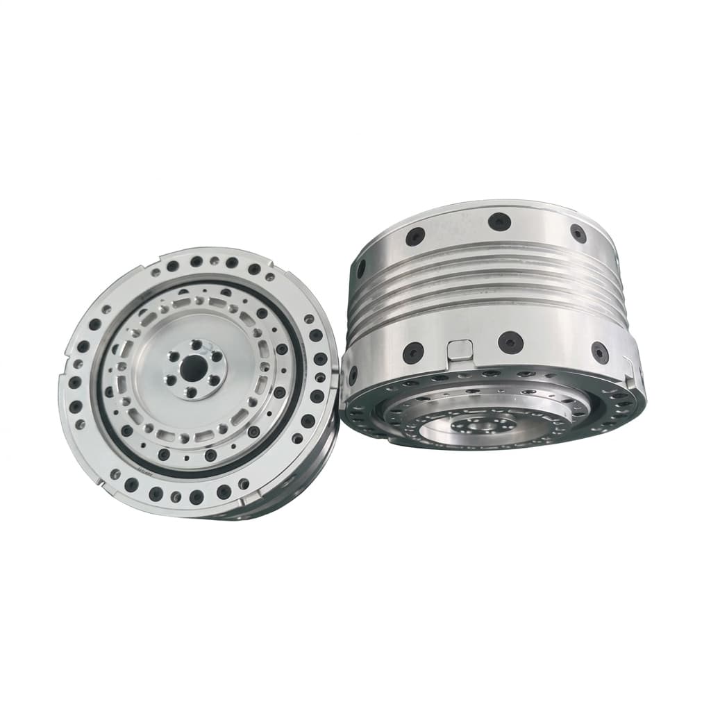
Hollow Shaft vs Solid Shaft Robot Joint Actuators: A Procurement and Engineering Guide
An in-depth analysis of hollow vs. solid shaft robot joint actuators. Learn how internal cable routing impacts torque density, sealing, cost, and procurement strategy.
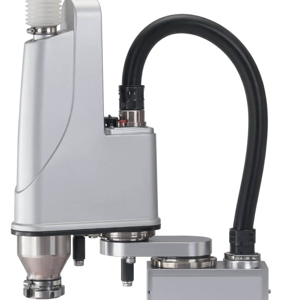
Functional Safety (SIL 3 / PL e) in Robot Joint Actuators: A 2026 Guide
Use this 2026 guide to evaluate SIL 3 / PL e robot joint actuators, STO/FSoE requirements, procurement checks, and RFQ questions for global cobot OEMs.
TCO Analysis for Robot Joint Actuators: Hidden Costs Beyond the BOM
Use this 2026 robot joint actuator TCO guide to price integration, tuning, yield, warranty, downtime, spares, and supplier risk before issuing an RFQ.