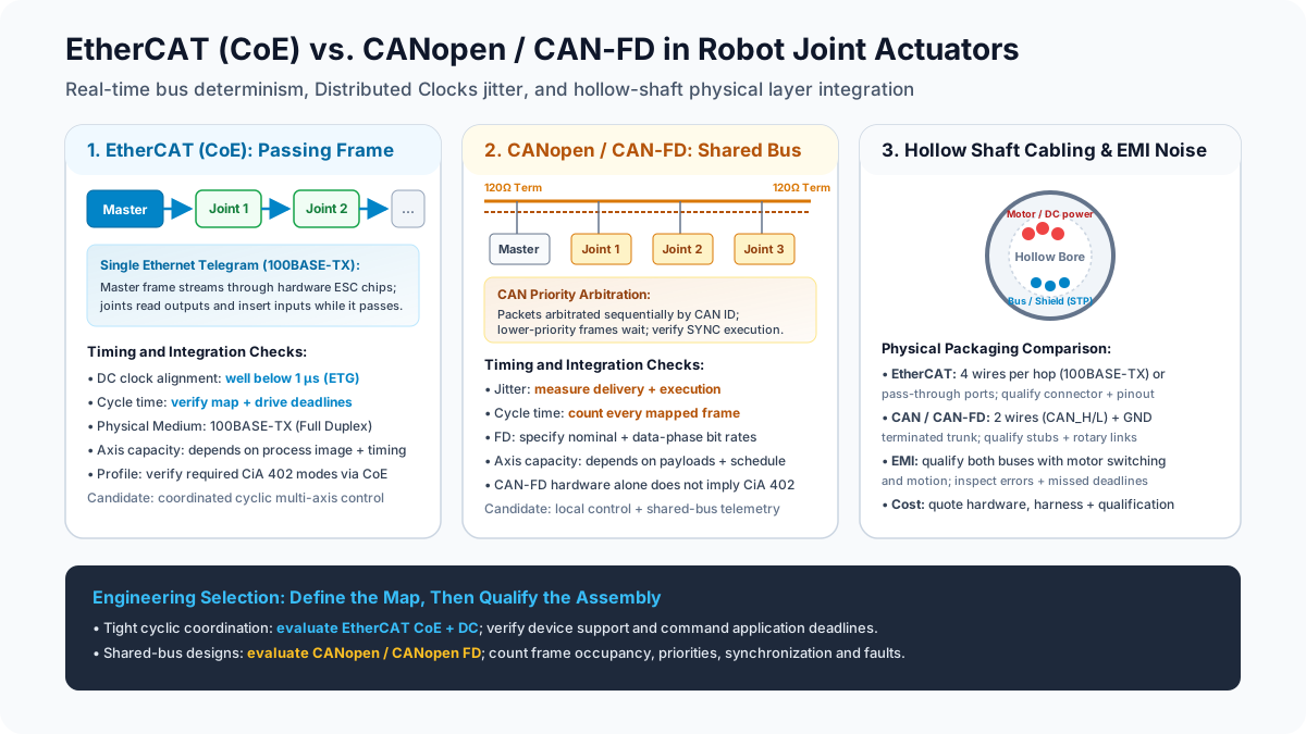
EtherCAT vs. CANopen / CAN-FD in Robot Joint Actuators: Real-Time Bus Jitter, Cycle Times, Daisy-Chain Cabling, and CiA 402 Integration (2026)
Compare EtherCAT vs CANopen and CAN-FD for robot joint actuators: cycle-time sizing, jitter, cabling and CiA 402. Use the checklist to prepare your supplier RFQ.
Content reviewed: November 9, 2026. This global engineering and procurement guide compares EtherCAT vs CANopen and CAN-FD for robot joint actuators. It is written for motion-control architects, embedded engineers, harness designers, and OEM buyers choosing interfaces for arms, humanoids, and mobile robots.
Scope: The comparison covers conventional 100BASE-TX EtherCAT with CAN application protocol over EtherCAT (CoE), Classical CANopen, and CANopen FD. CAN-FD alone identifies a data-link capability; a proprietary CAN-FD actuator is not automatically a CANopen FD or CiA 402 device. The calculations below are analytical examples, not measurements of our products or customer robots. No network choice establishes robot accuracy, gearbox life, or functional safety.
An integrated joint may combine a motor, reducer, encoders, brake, and drive, but its actual feature set varies. Mechanical sizing and communication design must be checked together: the selected interface needs to deliver the mapped process data before the drive's execution deadline while fitting the available hollow-bore harness.
Preparing a communication specification? Use the Robot Joint Actuator RFQ Template alongside the acceptance fields below.
Key Takeaways
- Separate synchronization from delivery: EtherCAT Distributed Clocks can synchronize participating device clocks to well below 1 µs according to ETG. That does not establish the master dispatch jitter, data age, or torque-loop execution timing of a complete robot.
- Count bytes and frames before selecting a cycle: In the example below, twelve full 8-byte Classical CAN frames need about 1.56 ms at 1 Mbit/s. That particular map cannot fit a 1 ms cycle, even before SYNC and diagnostics. Smaller maps, slower updates, or multiple buses change the decision.
- CAN-FD expands the design space: Payloads up to 64 bytes and a faster data phase can reduce occupancy. Application profiles, supported mappings, arbitration, and firmware deadlines still need verification; axis count alone does not define a universal limit.
- Qualify the harness: EtherCAT uses point-to-point links; CAN normally uses a terminated linear trunk with short stubs. Both need appropriate grounding, EMC design, and testing under motion and inverter switching.
- Compare complete integration cost: Request matched quotations for interface electronics, controller support, connectors, harnesses, firmware, and qualification. There is no defensible universal dollar premium per joint without a dated, volume-specific BOM.
1. The Multi-Axis Coordination Problem: Latency, Jitter, and Data Age
In many robot architectures, the central controller generates trajectory or torque targets while each actuator closes faster local current loops. A 1 kHz network update does not imply that the motor current controller also runs at 1 kHz. Ask which loops reside in the host and which reside in the drive.
Central trajectory / torque controller
        |  cyclic targets and feedback
        v
Fieldbus interface -> drive buffers / synchronization event
        |  local control loops
        v
Motor + reducer + encoder -> output flange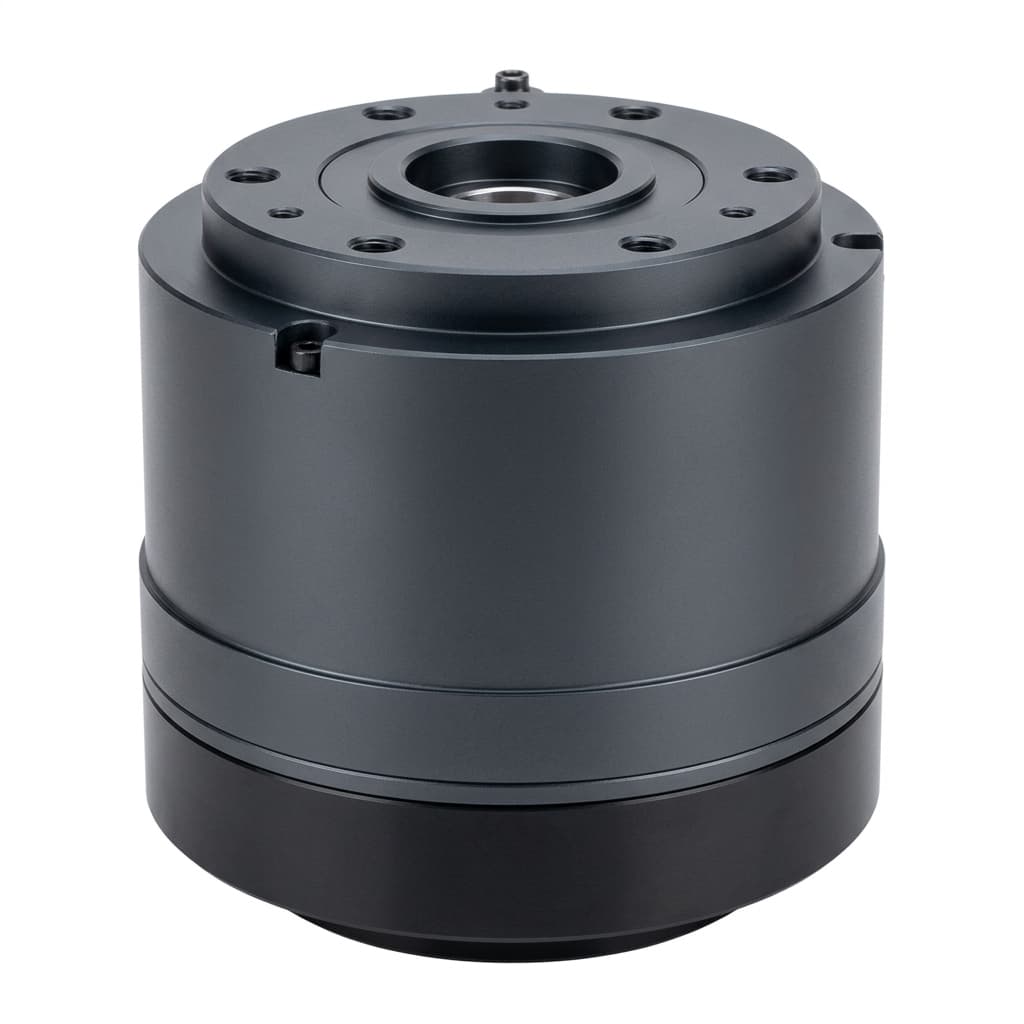
For qualification, distinguish four measurements: cycle period between scheduled updates, transport latency from transmission to delivery, synchronization skew between devices, and data age from feedback sampling to the corresponding applied command. A small value for one does not guarantee small values for the others.
A simple timing illustration explains why the distinction matters. Suppose position increments are 0.001 rad every nominal 1 ms. If a hypothetical receiver applies commands immediately on arrival and calculates velocity using arrival intervals, intervals of 0.75 ms and 1.25 ms correspond to 1.33 rad/s and 0.80 rad/s. These are arithmetic results for that receiver model, not measured disturbances in CANopen drives. A synchronous receiver that buffers commands and applies them at a defined event can behave differently.
Record the drive's actual application timing and behavior when a target misses its deadline. Arrival-time variation cannot by itself predict audible noise, flexspline fatigue, winding temperature, or tool-center-point accuracy. Those outcomes also depend on interpolation, control tuning, mechanics, and load.
2. EtherCAT (CoE) Deep Dive: "Processing-on-the-Fly" and Distributed Clocks
EtherCAT (Ethernet for Control Automation Technology, standardized in IEC 61158 and IEC 61784-2, maintained by the EtherCAT Technology Group under ETG.1000) was engineered specifically to eliminate Ethernet collision and arbitration bottlenecks in motion control.
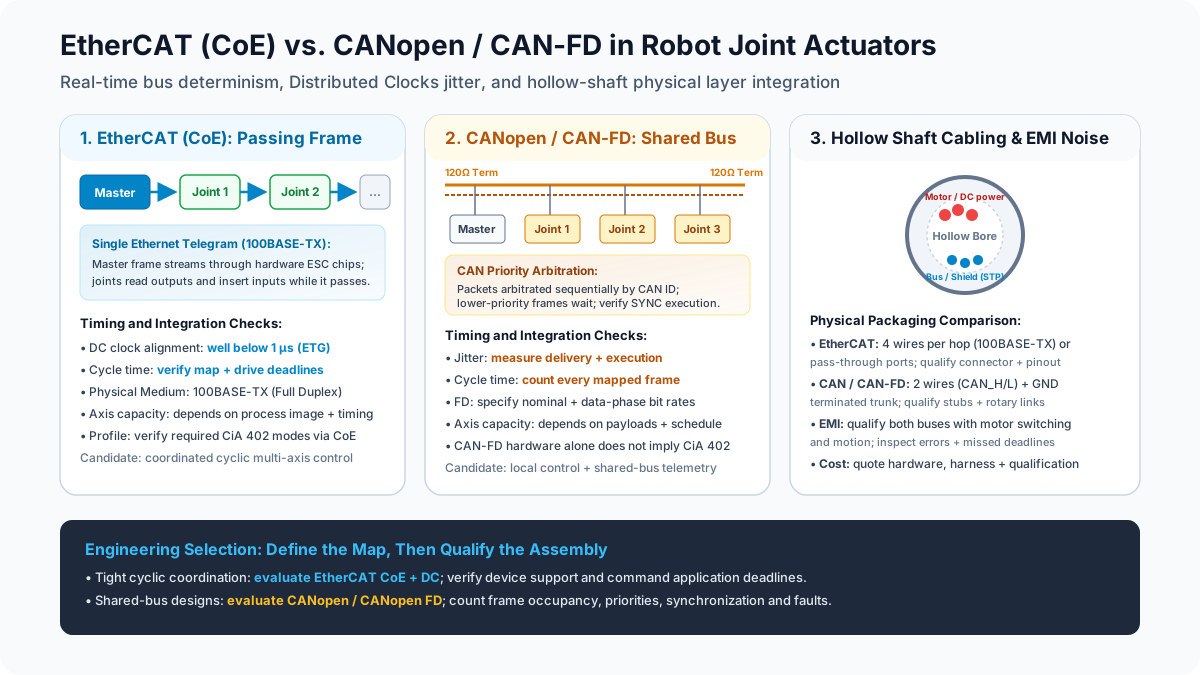
1. "Processing-on-the-Fly" Operating Principle
The master sends an Ethernet frame through the EtherCAT devices. Each EtherCAT Slave Controller (ESC) reads its assigned outputs and inserts inputs while the frame passes. The final device returns the frame toward the master over the full-duplex links. Device forwarding and cable propagation take finite time; one frame may cover many axes, but a larger process image can require additional frames.
The ETG technology overview describes this mechanism and Distributed Clocks. It does not certify a particular robot's cycle time or drive firmware.
2. Reproducible Transmission Budget Example
For an illustrative single-datagram EtherCAT exchange, let each of six axes occupy 24 process-image bytes in total. This is a chosen map size, not a mandatory CSP or CST payload. For one logical read/write datagram with non-overlapping input and output bytes, count the framing explicitly:
Process data P = 6 axes × 24 bytes = 144 bytes
Wire occupancy bytes = 8 preamble/SFD + 14 Ethernet header
                     + 2 EtherCAT header + 10 datagram header
                     + P + 2 working counter + 4 FCS + 12 inter-frame gap
                     = P + 52 = 196 bytes
Serialization / occupancy = 196 × 8 / 100 Mbit/s = 15.68 µs
This model has no VLAN tag, one datagram, and no extra mailbox or clock-maintenance traffic. Ethernet padding would matter for a smaller frame. The inter-frame gap is included as occupancy even though it is not frame data. Cable delay, device transit time, NIC handling, host scheduling, and drive execution are excluded. Consequently, 15.68 µs is not an end-to-end response time or a guaranteed minimum cycle. Different datagram mappings require a fresh count.
At a chosen 1 ms period, that serialization budget occupies 1.568% of the period. It demonstrates bandwidth headroom for this map; the supplier must still demonstrate timely delivery and execution at the requested cycle under the intended diagnostics load.
3. Distributed Clocks (DC) Synchronization Mechanism
DC-capable devices use synchronized local clocks, with propagation compensation, to schedule sampling or output events such as SYNC0. ETG describes device-clock synchronization substantially below 1 µs. Verify that the actuator supports the required DC mode and couples the event to its control firmware.
Measure device-clock skew separately from host dispatch jitter and command-to-output delay. Buffered outputs can tolerate variation in frame arrival when every command arrives before its configured latch deadline. A missed deadline remains a fault or stale-data event; there is no universal rule that half a cycle of master jitter is acceptable.
4. CiA 402 Integration over CoE
CoE lets a drive expose an object dictionary with familiar control and feedback objects. The supplier must identify which CiA 402 functions and modes it implements; support for the communication transport alone is insufficient.
0x6040: Controlword for drive-state commands.0x6041: Statusword for state feedback.0x6060/0x6061: Requested / displayed operating mode.0x607A: Target position.0x6071: Target torque.0x6064: Actual position; confirm motor/output reference, units, and scaling.0x6077: Actual torque; confirm scaling and how the value is derived.
Require an EtherCAT Slave Information (ESI) XML file matching the exact firmware. Import it into the selected master, confirm PDO assignments and units, and test the state-machine sequence. ROS 2 integration also requires an appropriate hardware interface and real-time scheduling; an ESI file alone does not provide that integration. Include fault reset, enable, disable, mode switching, and restart behavior in the sample acceptance plan.
3. CANopen and CAN-FD: Arbitration and Bandwidth Sizing
Classical CANopen uses the CiA 301 application and communication profile over Classical CAN. CANopen FD uses CiA 1301 over CAN FD. CiA 402 describes drive behavior and mappings; request the exact supported parts and versions instead of treating these names as interchangeable.
1. Priority Arbitration on a Shared Bus
CAN frames share a bus. When transmissions start together, non-destructive bitwise arbitration selects a winning identifier; losing nodes wait and retry. An already transmitting lower-priority frame is not interrupted by a newly queued higher-priority frame. Its remaining transmission time contributes blocking delay.
CANopen SYNC and synchronous PDO handling can coordinate application actions, so arrival-time variation is not automatically execution skew. Worst-case response time depends on priorities, release patterns, frame lengths, controller queues, error recovery, and the receiver's scheduling. Node position along the cable does not determine arbitration priority.
2. Classical CANopen Wire Time Calculation
For an 11-bit identifier data frame with d payload bytes, include the three-bit intermission in the fixed count:
t_frame = (47 + 8 × d + s) / bitrate
s = inserted stuff bits, dependent on the actual bit pattern
For a chosen full 8-byte frame and an illustrative 19 stuff bits, the result at 1 Mbit/s is (47 + 64 + 19) / 1,000,000 = 130 µs. The assumed stuffing count is not a worst-case bound; use actual frame encodings or a conservative bound for acceptance analysis.
If six drives each receive one 8-byte command PDO and send one 8-byte feedback PDO per cycle, twelve frames need 12 × 130 µs = 1.56 ms. Even without stuffing, twelve such frames need 1.332 ms. Therefore, this map cannot meet a 1 ms cycle on one 1 Mbit/s bus. SYNC, heartbeat, EMCY, configuration traffic, and retransmissions consume additional capacity.
At 5 ms, the illustrative PDO load is 31.2%; at 10 ms it is 15.6%, before other traffic. These are candidate periods for evaluation, not mandatory CANopen cycle limits. A smaller map, reduced feedback frequency, locally generated profiles, or independent buses can change the result. Excess offered traffic causes missed deadlines or queue overflow; saturation alone does not necessarily create physical CAN error frames.
3. What CAN-FD Changes
CAN-FD permits up to 64 payload bytes and an optional faster data phase. Arbitration and other nominal-rate fields remain overhead. For example, specifying 1 Mbit/s nominal and 5 Mbit/s data rates does not make the whole frame five times faster. Include the selected payload length, CRC and stuffing rules, and both bit rates in the frame-time analysis.
Do not assume that a master can pack commands for every actuator into one arbitrary 64-byte broadcast. Each drive must support and interpret the selected mapping. The official CiA overview identifies CiA 402-6 as a CANopen FD PDO mapping specification. Proprietary CAN-FD command formats require their own protocol documentation.
For an RFQ, provide a frame inventory with identifier, producer, payload, period, deadline, and priority for each message. Ask the supplier to return worst-case delivery and execution evidence under normal and diagnostic traffic. This is more useful than a generic claim of a 1 kHz bus or a fixed maximum axis count.
4. Physical Integration: Daisy-Chain Cabling, Hollow Bores, and EMI
1. Design the Complete Signal Path
Conventional 100BASE-TX EtherCAT uses two twisted pairs, four signal conductors per link. A pass-through line node generally needs two ports; the end node can use one. Counting both incoming and outgoing links gives eight signal terminations at an intermediate module, but the bore conductor count depends on the actual harness route. Junction devices and other EtherCAT physical-layer variants are outside this comparison.
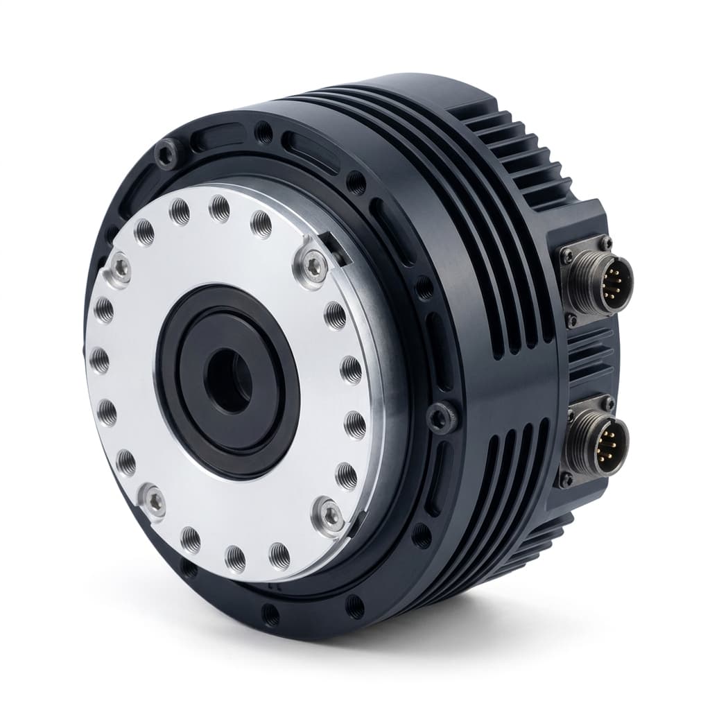
High-speed CAN and CAN-FD normally use a linear differential trunk with short stubs. Plan CAN_H, CAN_L, the reference/ground arrangement, and shielding or isolation as required by the transceiver design. A smaller signal pair count can help a compact wrist, but it does not establish slip-ring reliability.
Ask for connector manufacturer, full part number, coding, pinout, shield contact, and cable assembly drawing. A label such as M8, JST, or Hirose alone does not establish Ethernet suitability. Hybrid power/data connectors require confirmation of both signal integrity and electrical ratings.
2. Qualify EMI and Motion Together
Motor inverter switching can couple noise into either bus. Susceptibility depends on edge rates, cable geometry, bonding, isolation, common-mode range, and PCB layout. Neither a 48V supply label nor a protocol name provides an EMC immunity rating. Do not confuse a transceiver's operating common-mode range with its bus-fault survival voltage.
Specify suitable differential impedance and pair construction for the selected physical layer, dynamic bend radius, torsion limits, shield bonding, and separation from switching conductors. Request flex-life evidence for the actual cable at the intended bend radius and motion profile rather than importing a universal cycle rating.
Test the assembled harness while moving the joints and switching representative motor loads. Record link losses, CRC/error counters, bus-off events, and missed application deadlines. Slip rings must be qualified for the chosen data rate, rotation speed, wear condition, and environment. A generic continuity test is insufficient for either protocol.
Communication loss does not define brake behavior. Document and test watchdog settings, stop sequencing, brake timing, and gravity-load handling as part of the system's safety design.
5. Fieldbus Comparison Matrix for Engineering and Procurement
The matrix compares interface mechanisms and evidence to request. Cycle-time and cost entries are conditional because neither is fixed by the protocol alone.
| Technical and procurement dimension | EtherCAT (CoE) | CANopen FD | Classical CANopen |
|---|---|---|---|
| Application profile | CoE; verify CiA 402 support | CiA 1301; verify CiA 402 parts including FD mapping | CiA 301; verify CiA 402 support |
| Physical link in this guide | 100BASE-TX, 100 Mbit/s | CAN FD; negotiate nominal and data bit rates | High-speed Classical CAN, up to 1 Mbit/s |
| Data exchange | Passing frame reads/writes process image | Prioritized shared-bus frames | Prioritized shared-bus frames |
| Payload planning | Count Ethernet/datagram overhead and process image | Up to 64 bytes per data frame | Up to 8 bytes per data frame |
| Application synchronization | DC if supported and configured | Verify SYNC and actual drive execution behavior | Verify SYNC and actual drive execution behavior |
| Jitter evidence | Clock skew, master dispatch, and output timing separately | Worst-case frame response and application skew | Worst-case frame response and application skew |
| Six-axis example | 15.68 µs serialization for the stated 144-byte map; other delays excluded | Recalculate using actual mappings and both rates | 1.56 ms for twelve full PDOs with assumed stuffing |
| Cabling topology | Point-to-point line with pass-through ports | Terminated linear trunk with short stubs | Terminated linear trunk with short stubs |
| Signal conductors | Two twisted pairs per link | Differential pair plus reference/shield design | Differential pair plus reference/shield design |
| Configuration deliverable | Firmware-matched ESI XML and PDO map | Supported electronic description and FD mapping | EDS/DCF and PDO map |
| EMC and slip rings | Qualify complete moving assembly | Qualify complete moving assembly | Qualify complete moving assembly |
| Cost comparison | Quote controller, interface, harness, software, and qualification | Quote the same scope and production volume | Quote the same scope and production volume |
Use the RFQ template to request the same evidence from each supplier before comparing commercial offers.
6. Worked Selection Scenarios: Match the Bus to the Control Architecture
These are hypothetical design reviews, not customer test results. The update periods are selected requirements for each example.
Scenario A: Six-Axis Arm with a 1 ms Cyclic Target
Start with the twelve full 8-byte PDOs in Section 3. A single Classical CAN bus fails that bandwidth requirement before any safety or trajectory assessment. EtherCAT is a strong candidate because the example process image has substantial serialization headroom and DC provides an explicit synchronization mechanism. CAN-FD remains a candidate if the actual profile, full traffic inventory, and drive deadlines pass analysis and testing.
Do not turn that conclusion into a claim that every six-axis arm needs EtherCAT. An arm using local trajectory generation or a different feedback map has different requirements. Specify command age and inter-axis application skew, then measure those at the drive interface. Network choice alone cannot guarantee a particular repeatability value.
Scenario B: Fourteen-Axis Legged Robot with a 500 µs Target
A shared low-rate bus becomes difficult as command and feedback traffic grows. EtherCAT is a reasonable architecture to evaluate for centralized cyclic torque control, provided each drive supports the required cycle and timing. Multiple CAN-FD segments can also be evaluated; include controller port count, cross-segment synchronization, software scheduling, and fault containment in the comparison.
Do not call either architecture mandatory from axis count alone. Determine which stabilization loops run locally and how old feedback may become before control quality is unacceptable. Require a complete timing trace under representative compute load and diagnostics. Clock synchronization cannot prove balance stability or simultaneous inverter switching.
Scenario C: Mobile Base with Four Drive/Steer Axes at 10 ms
For the same illustrative one-command/one-feedback frame map, eight Classical CAN frames take 1.04 ms, or 10.4% of a 10 ms period before other traffic. CANopen is therefore worth evaluating when the vehicle controller already supports it. CAN-FD may offer more telemetry capacity.
EtherCAT can still be justified by an existing controller ecosystem, synchronized tooling, or a common service strategy across machines. Compare integration and lifecycle cost instead of claiming it offers no benefit at a particular vehicle speed. Count a payload lift or auxiliary axis separately if it shares the bus.
7. The OEM Procurement & RFQ Technical Acceptance Checklist
When drafting an RFQ for integrated robot joint actuators, generic requests like "Actuator must support EtherCAT or CAN" lead to integration failures. Require suppliers to confirm compliance with these eight specific technical fields:
- 1. Exact Protocol Profile & Standard Compliance: Specify standard and profile version explicitly (e.g., EtherCAT CoE conforming to ETG.1000 and CiA 402 / IEC 61800-7-201, or CANopen FD conforming to CiA 1301 and CiA 402). Request available conformance evidence tied to the exact product and firmware; distinguish an independent certificate from a supplier declaration.
- 2. Supported CiA 402 Motion Modes: Verify that the actuator's firmware supports your required operational mode: Cyclic Synchronous Position (CSP,
0x6060 = 8), Cyclic Synchronous Velocity (CSV,0x6060 = 9), Cyclic Synchronous Torque (CST,0x6060 = 10), Profile Position (PP,0x6060 = 1), or Homing (0x6060 = 6). Confirm support in the supplied firmware instead of inferring it from an EtherCAT or CANopen label. - 3. Minimum Cycle Time and Hardware Jitter: Require written verification of the minimum verified bus cycle time (e.g., 250 µs for EtherCAT or 1 ms for CAN-FD, if those are your chosen targets) and execution jitter relative to the configured timing event (
SYNC0for applicable EtherCAT DC modes, or the documented CAN synchronization scheme). Include the complete PDO map and diagnostics load. - 4. Configuration File Provision (ESI / EDS): Mandate that the supplier deliver tested, error-free EtherCAT Slave Information (
.xmlESI) or CANopen electronic description (EDS/DCF or the supported FD format) files matching the exact firmware build before pilot sample dispatch. - 5. Physical Connector Form Factor & In/Out Topology: Confirm connector part numbers and the tested pinout. Confirm separate line ports where EtherCAT pass-through is required; document the end-node arrangement and avoid passive Ethernet T-splitters.
- 6. Hollow-Bore Shielding & Differential Impedance: For hollow-shaft models, specify cable construction: impedance-controlled twisted pairs and shield bonding appropriate to the selected physical layer, plus verified bend/torsion ratings for the actual motion envelope.
- 7. EMC, Isolation, and Fault Response: Request the PHY/transceiver ratings, isolation boundary and test conditions, EMC evidence, watchdog behavior, and stop/brake sequence. A common-mode choke or transformer alone does not prove system immunity or safety.
- 8. Multi-Drop Termination & Node ID Setting: For CAN/CAN-FD actuators, verify whether the 120 Ω termination resistor is software-configurable or jumper-selectable, and confirm whether Node IDs are configured through the documented commissioning method, such as supported LSS, hardware switches, or vendor configuration tools; do not assume a universal object index.
8. Frequently Asked Questions (FAQ)
Q1: Can EtherCAT run through a continuously rotating slip ring?
Yes, if the entire rotary link is qualified for 100BASE-TX under the required speed, wear, and environment. Request signal-integrity and error-rate evidence for the actual assembly. A CAN link also requires qualification; fewer conductors do not make a generic slip ring suitable. Contactless rotary data joints or a separately controlled tool network may be alternatives.
Q2: Why can an EtherCAT actuator lack CSP mode?
EtherCAT describes communication, while CSP is a drive application mode. CoE support does not establish every optional CiA 402 capability. Check supported modes, object 0x6060, mode display 0x6061, PDO mapping, units, and the minimum accepted cycle. CSP does not universally require a particular interpolation polynomial or exactly a 1 ms period.
Q3: What happens when an EtherCAT frame is lost?
The master can detect missing or inconsistent process data through frame monitoring and working-counter checks. Drive watchdogs and application settings determine the response to stale data. There is no universal allowance of two lost frames or automatic brake sequence after three. A CiA 402 Quick Stop is not itself a safety-rated emergency stop. Validate the configured stop sequence, load support, and brake operation for the machine.
Q4: Can one robot combine EtherCAT and CANopen actuators?
Yes, with separate interfaces or a supported gateway. Account for gateway latency, feedback age, time-domain alignment, and fault propagation. A typical architectural option is a synchronized main joint network with a separate tool or gripper bus; whether it works depends on the tool's required timing and stop coordination.
Q5: Is CAN-FD backward compatible with Classical CANopen hardware?
An FD-capable controller can often operate using Classical CAN frames. That does not make active FD traffic compatible with every legacy node. An FD-intolerant Classical CAN controller can signal errors when it encounters an FD frame, even before the faster data phase. Compatibility involves the controller and protocol stack as well as the transceiver. FD-tolerant legacy devices are a separate case; confirm every node's capability and the application's permitted mixture.
Q6: Does Linux or TwinCAT determine Distributed Clock precision?
DC uses participating device clocks; host operating-system scheduling is a separate timing concern. Either host stack must deliver process data before the configured application deadline. Compare measured worst-case dispatch, latch timing, and deadline misses on the intended hardware under load. A generic operating-system name is insufficient evidence for a numerical jitter ranking.
Q7: Does EtherCAT cable redundancy guarantee uninterrupted motion?
A supported redundant topology can preserve connectivity after certain cable breaks. It requires the appropriate master, configuration, and return path, and does not cover all device failures. Check the supported fault cases and measured recovery behavior. Continued motion after a fault must follow the machine's approved control and safety design.
Q8: Does CAN-FD need a termination resistor at every joint?
No. For a conventional high-speed CAN/CAN-FD linear bus, use a nominal 120 Ω termination at each physical end, with intermediate terminations disabled. Two simple 120 Ω resistors appear as about 60 Ω in parallel when measured on a suitable powered-off assembly; follow the hardware manufacturer's procedure. Six such resistors would total 20 Ω, not a fraction of an ohm. Split termination or isolated networks need interpretation according to their schematics.
9. Sources, Methodology, and Limits
Source scope and links reviewed on November 9, 2026:
- EtherCAT Technology Group — Technology Overview: Primary reference for frame processing, Distributed Clocks, topology, and CoE. Its technology-level capabilities do not establish any actuator's measured timing.
- CAN in Automation — CiA 402 Series: Official overview of the drive profile and related mappings, including CANopen FD and the relationship to IEC 61800-7. It also identifies optional implementation differences relevant to supplier integration.
- ISO — ISO 11898-1:2015 catalogue record: Historical reference for Classical CAN and FD frame capabilities. The record marks this edition withdrawn and superseded by ISO 11898-1:2024. Agree the applicable edition with the supplier; this older record is not evidence of current product compliance.
Engineering methodology: The worked examples use explicitly selected payloads, frame counts, rates, and stuffing assumptions. They are reproducible screening calculations, not hardware benchmarks or worst-case certification. The visual is a conceptual architecture diagram; the product photographs illustrate packaging and do not prove a particular interface option.
Limits and acceptance: No supplier-specific jitter, EMC, cost, reliability, or robot accuracy measurements are claimed. Validate the final PDO map, master, firmware, cable assembly, and diagnostic traffic together. Keep a record of sample count, duration, loading, maximum observed timing error, and deadline misses. A zero-miss test run is evidence for those conditions, not proof of an absolute bound. Repeat qualification when firmware, mappings, or the moving harness change.
10. Next Steps for Procurement & Engineering Teams
Before releasing your robotic joint actuator specification to suppliers, ensure your electrical and software engineering teams have aligned communication bus capabilities with your real-time motion control requirements:
- Review the Robot Joint Actuator Selection Guide for comprehensive sizing rules across motor frameless sets, gearheads, and drive electronics for 6-axis cobots and mobile robots.
- Copy and customize the Robot Joint Actuator RFQ Template, ensuring you attach the eight communication specification items outlined above, including cycle time targets, CiA 402 modes, connector types, and ESI/EDS file deliverables.
- Explore our complete Robot Joint Actuator Product Range, and ask which communication options are available on the exact model and firmware. Request supporting certificates or test records rather than assuming every listed unit has a certified interface.
- For technical consultation, sample ESI configuration files, or custom hollow-shaft pinout drawings, contact our engineering support team directly via our Contact / RFQ Portal. Provide your target axis count, loop cycle time (1 kHz or 500 Hz), supply voltage (24–48 V), and host controller stack, and process-data map to request a compatibility review and an agreed sample qualification plan.
Author

Categories
More Posts
Prototype to Mass Production: 12 Gate Plan for Joint Actuators
A 12-gate execution model for robot joint actuator programs covering prototype validation, CTQ control, compliance file readiness, and production-release criteria with timeline estimates and cost-of-failure analysis.

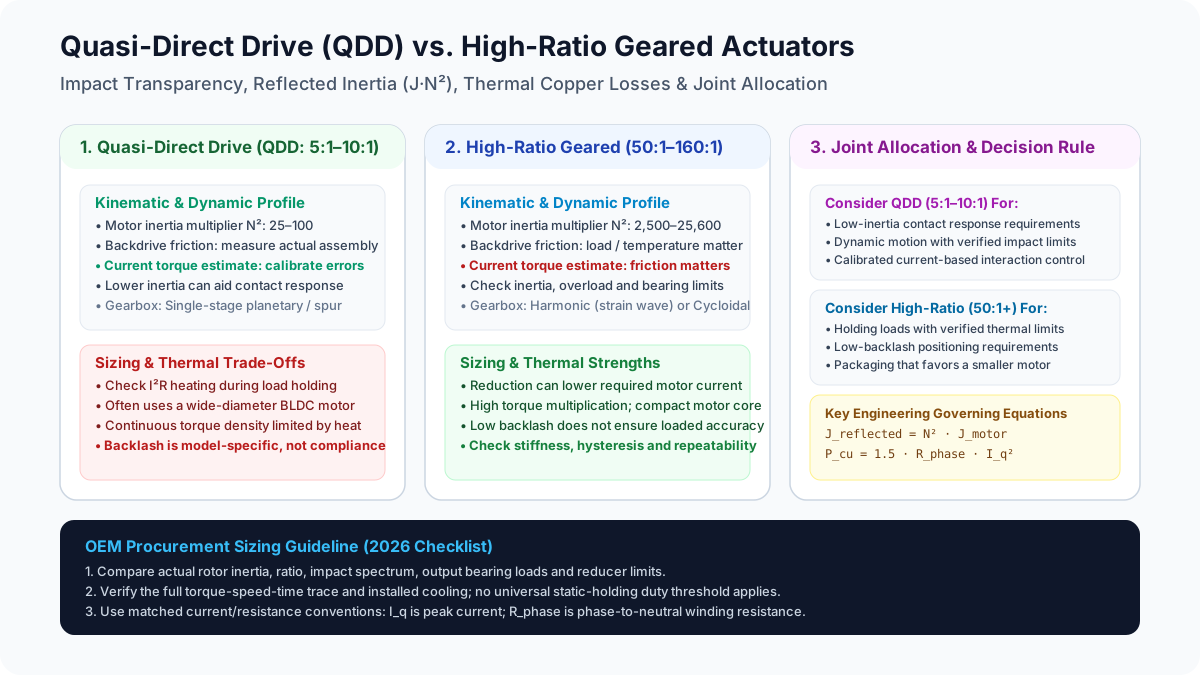
Quasi-Direct Drive (QDD) vs. High-Ratio Geared Actuators in Robot Joints: Reflected Inertia, Impact Transparency, and Thermal Sizing (2026)
Compare QDD vs high-ratio robot joint actuators by reflected inertia, impact response, and thermal sizing. Use the engineering checklist to prepare your OEM RFQ.
Integrated vs. Discrete Robot Joint Actuators: A 2026 TCO and Procurement Guide
Compare integrated vs. discrete robot joint actuators for 2026 TCO, BOM, labor, supply risk, MTTR, and RFQ decisions for OEM teams.