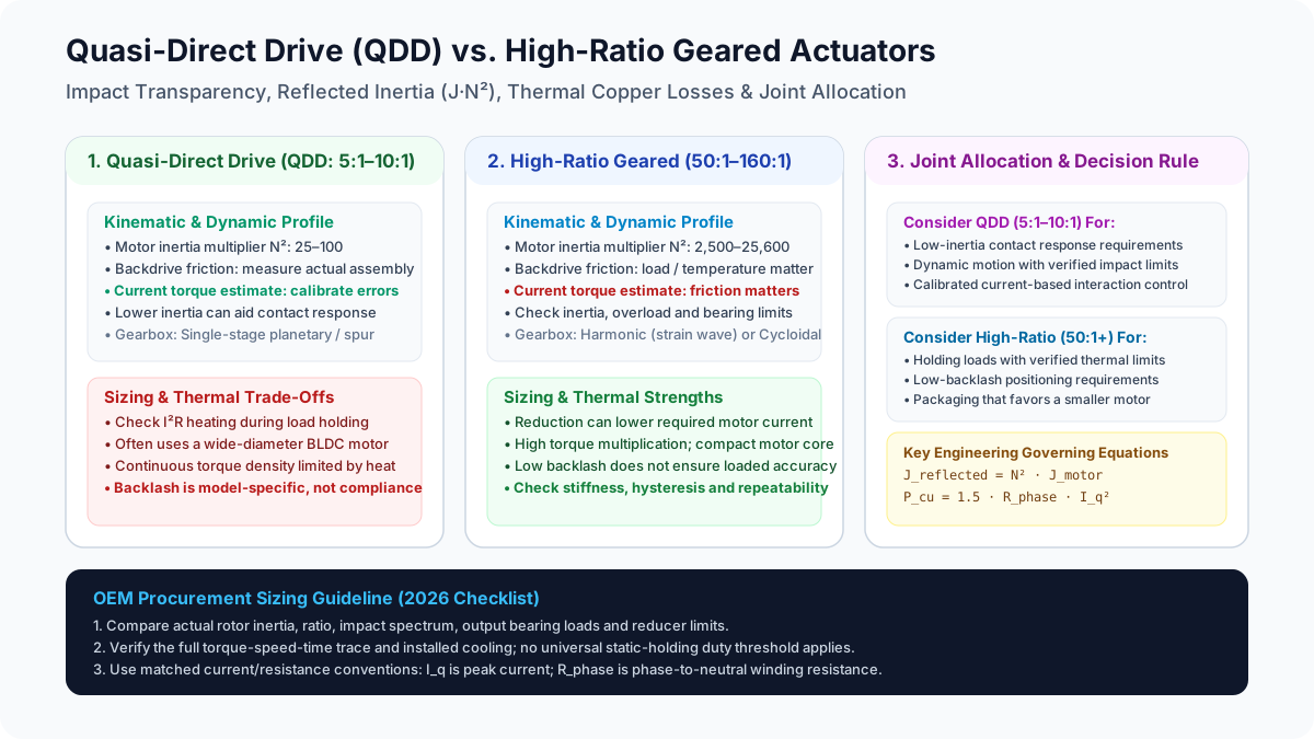
Quasi-Direct Drive (QDD) vs. High-Ratio Geared Actuators in Robot Joints: Reflected Inertia, Impact Transparency, and Thermal Sizing (2026)
Compare QDD vs high-ratio robot joint actuators by reflected inertia, impact response, and thermal sizing. Use the engineering checklist to prepare your OEM RFQ.
Content reviewed: November 6, 2026. This guide is for robot OEM systems architects, mechanical design leads, motion control engineers, and procurement teams worldwide evaluating Quasi-Direct Drive (QDD) vs. high-ratio geared actuators for robot joints.
Choose a low-ratio QDD candidate when contact response and low reflected motor inertia are priorities. Evaluate higher reduction when continuous load torque and motor packaging dominate. Neither architecture guarantees impact survival, contact safety, precision, or acceptable temperature by itself.
Scope and evidence: This is an engineering screening guide for rotary electric joints, not a product qualification report. The numerical examples use explicitly assumed parameters; they are reproducible calculations, not physical tests or supplier ratings. Ratio ranges are working definitions for this comparison, not an industry standard. Final selection requires model-specific torque-speed curves, thermal conditions, reducer limits, and application testing.
Key Takeaways
- Compare actual reflected inertia: The motor contribution at the output is
J_refl = N² × J_motor. A lower ratio reduces this contribution for the same rotor, but QDD motors can have higher rotor inertia. The worked example below gives a 31.6-fold difference, not a universal architecture multiplier. - Check current-based torque estimation: Low friction can improve proprioceptive control. Gravity, acceleration, cogging, seals, and temperature still affect accuracy; current sensing does not automatically replace an output torque or wrist force-torque sensor.
- Size for heat over the mission: Copper loss grows with current squared. Compare winding resistance, torque constant, cooling, and the actual torque-time profile rather than peak torque alone.
- Separate backlash from useful compliance: Tooth clearance can create lost motion and reversal impacts. It is not controlled elasticity or evidence of collision safety.
- Allocate joints by their loads: A mixed actuator architecture is an option, not a universal 2026 industry rule. Screen every axis against impact, continuous load, speed, accuracy, and packaging requirements.
Preparing an RFQ? Use the OEM actuator sourcing checklist to define the evidence needed from competing suppliers.
Architectural Definitions: Direct Drive vs. QDD vs. High-Ratio
For this comparison, the three architectures mean:
- Direct Drive (DD, N = 1): The load couples directly to the rotor, removing reducer backlash and reducer friction. Bearings, seals, cogging, rotor inertia, and structural load limits remain. Required motor size depends on continuous torque, cooling, and allowable diameter; direct drive has finite shock tolerance.
- Quasi-Direct Drive (QDD, approximately N = 5–10): A torque-dense motor uses a low-ratio reduction, often a single-stage planetary or spur train. This can preserve backdrivability while multiplying motor torque, but friction and rotor inertia must be measured for the actual assembly. Other designs described as QDD can fall outside this illustrative ratio band.
- High-Ratio Geared Actuators (approximately N = 50–160): A smaller, faster motor drives a strain-wave or cycloidal reducer. Reduction increases output torque per motor ampere and reduces output speed. Strain-wave and cycloidal mechanisms have different stiffness, hysteresis, efficiency, and overload behavior; they should not be treated as interchangeable. High reduction does not establish self-locking or power-off holding capability.
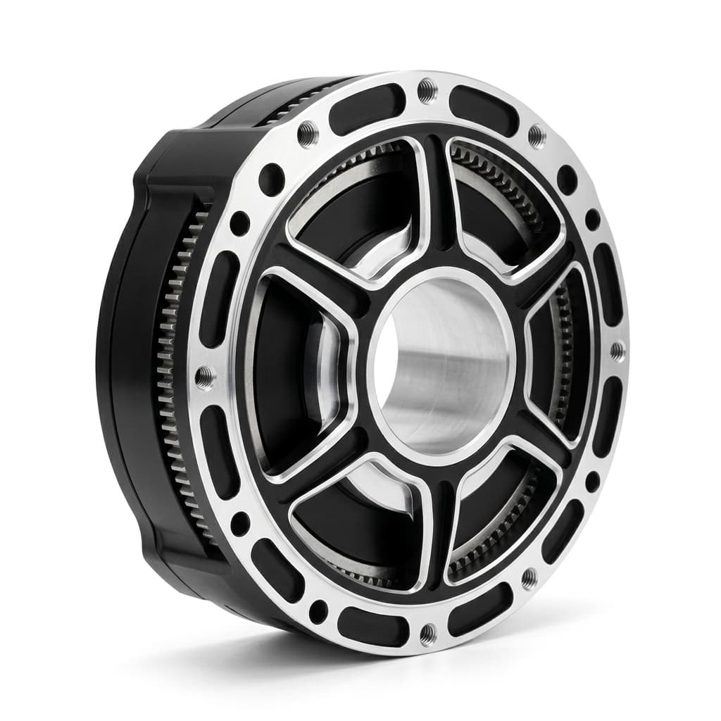 Figure 1: Product illustration of a planetary QDD module. Confirm ratio, encoder, driver, and torque ratings in the specific model datasheet; the photograph does not establish these specifications.
Architectural Comparison Diagram
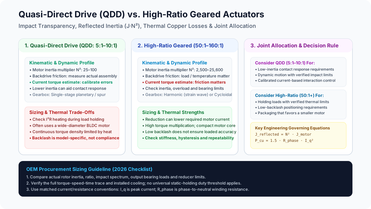 Figure 2: Conceptual comparison of inertia, copper-loss sizing, and selection questions. These are screening relationships, not measured product performance.
Reflected Inertia and Impact Mechanics: The N² Relationship
For a rigid, single-axis transmission, the motor rotor contributes the following inertia at the joint output:
J_refl = N² × J_motor
J_joint = J_load + J_gearbox,out + J_refl
Here N = motor speed / output speed; inertia is in kg·m². J_gearbox,out must include each moving gearbox component referred to the output, rather than simply adding its physical inertia. Compliance, friction, and other robot axes make the complete contact dynamics more complicated than this lumped model.
Numerical Comparison of Reflected Inertia
These are hypothetical input parameters for arithmetic comparison. They do not establish equal continuous torque, mass, cost, or impact ratings.
| Parameter | Configuration A: High-Ratio Harmonic Actuator | Configuration B: QDD Module |
|---|---|---|
| Gearhead type | Strain-wave | Single-stage planetary |
| Reduction ratio N | 100:1 | 8:1 |
| Assumed rotor inertia J_motor | 0.000085 kg·m² | 0.000420 kg·m² |
| Ratio multiplier N² | 10,000 | 64 |
| Reflected motor inertia | 0.850 kg·m² | 0.02688 kg·m² |
| Reflected motor inertia relative to B | 31.6 times | 1 time |
Configuration B has about five times the physical rotor inertia, yet much less reflected motor inertia. Rotor inertia alone says nothing about rotor mass without geometry. Also, the 31.6 ratio is not a ratio of total contact impedance: link inertia, contact stiffness, damping, and controller behavior remain outside this calculation.
Why Control Bandwidth Does Not Establish Impact Survival
An active controller cannot remove physical rotor inertia. Whether it can reduce a particular collision load depends on contact duration, sensing latency, closed-loop bandwidth, saturation, and the mechanical compliance between the contact and motor. Fast contact may excite flexible modes before the controller produces a useful response; slower contact can be influenced by feedback. A universal statement that feedback is ineffective for the first five milliseconds is unjustified.
Lower reflected inertia can reduce inertial resistance to externally imposed joint motion. It does not guarantee that a planetary gearset survives a fall, or that a high-ratio reducer fails. Verify peak and repeated reducer torque, output-bearing loads, contact energy, and any compliant elements. When backdriving generates electrical energy, the battery, bus capacitor, or braking circuit must accept it without overvoltage; back-EMF alone is not an energy sink.
Wensing et al. (2017) provide the actuator-design context for low inertia and impact mitigation in the MIT Cheetah. Their platform evidence does not qualify every low-ratio actuator for impact service.
Thermal Dissipation and Continuous Torque Sizing
QDD can need more motor torque for a given output load because it has less reduction. However, copper heating depends on the motor as well as the ratio. A larger motor with a better motor constant can change the comparison substantially.
For the following equations, assume sinusoidal currents, negligible reluctance torque, peak-amplitude q-axis current I_q, a torque constant defined against that same current, and phase-to-neutral winding resistance R_phase at the stated temperature:
T_motor = K_t × I_q
P_cu = 1.5 × R_phase × I_q²
For a balanced star-connected motor, line-to-line DC resistance is twice phase resistance. Do not insert a supplier's line-to-line resistance or RMS torque constant into these equations without conversion. Delta windings and alternative controller current conventions require their own conversion.
During motoring at a defined speed and load, a simplified output relationship is:
T_out = N × eta_gear × T_motor
P_cu = 1.5 × R_phase × (T_out / (N × eta_gear × K_t))²
The inverse-square ratio trend holds only with the other quantities fixed. Different motors, changing gear efficiency, and speed-dependent losses prevent it from being a universal system-efficiency law.
Static Load Holding: An Explicitly Idealized Comparison
At zero speed, mechanical output power is zero, so running efficiency is not a reliable static torque-transfer model. To isolate motor copper heating, assume ideal torque transfer (T_motor = T_out / N) and no assistance from gearbox friction or a brake. Use a constant 30 N·m output load and the following hypothetical parameters:
Case 1: QDD
N = 8; K_t = 0.18 N·m/A_peak; R_phase = 0.22 ohm
T_motor = 30 / 8 = 3.75 N·m
I_q = 3.75 / 0.18 = 20.83 A_peak
P_cu = 1.5 × 0.22 × (20.83)² ≈ 143.2 W

Case 2: High-ratio
N = 100; K_t = 0.065 N·m/A_peak; R_phase = 0.85 ohm
T_motor = 30 / 100 = 0.30 N·m
I_q = 0.30 / 0.065 = 4.62 A_peak
P_cu = 1.5 × 0.85 × (4.62)² ≈ 27.2 W
This is a 5.3-fold difference for these inputs, not a general QDD penalty. Both estimates exclude inverter loss; moving duty also adds iron, friction, and gearbox loss. Resistance rises as copper warms, so a cold-resistance estimate can understate hot copper loss. Static friction may reduce the current needed to hold in one load direction but should not be assumed to provide dependable power-off support.
Temperature rise needs a thermal model. For example, an assumed winding-to-ambient thermal resistance of 3 K/W and allowable rise of 75 K yields a 25 W steady-state heat budget. Under that simplified boundary, both examples exceed the budget. Actual limits depend on the mounting structure, ambient temperature, winding limit, rotor magnet limit, and thermal interfaces. Without thermal resistance and heat capacity, neither a time to cutoff nor indefinite operation can be predicted.
Duty-Cycle Screening Before a Supplier Quote
For piecewise-constant torque, use T_RMS = sqrt(sum(T_i² × duration_i) / total_duration) as an initial screen when torque-to-current conversion is approximately constant. An illustrative cycle of 30 N·m for 25% of the time and 10 N·m for 75% gives 17.32 N·m RMS. In the idealized examples, average copper loss becomes about 47.7 W and 9.1 W respectively. This does not check peak current, peak-duration limits, or speed-voltage constraints.
Ask suppliers to evaluate the full torque-speed-time trace at the installed cooling condition. A catalog continuous rating taken on a large heat sink may not apply inside a sealed robot limb. Record the winding temperature at the end of a repeated mission, not just the outer housing temperature after a short demonstration.
Proprioceptive Force Sensing vs. Dedicated Torque Sensors
Motor current estimates electromagnetic motor torque. To estimate contact torque at the output, subtract modeled friction, acceleration, gravity, and other known loads, using a consistent sign convention. For example, with positive contact torque defined as torque the robot applies to its environment:
tau_contact,estimate = tau_drive,out - tau_friction - tau_gravity - tau_dynamicHere tau_dynamic includes the modeled inertial and velocity-dependent robot terms. Gear compliance, torque-constant calibration, current offset, and temperature affect the residual. A low-ratio transmission often makes the friction correction smaller, improving torque transparency, but that is a design tendency rather than an accuracy specification.
When Additional Torque Sensing Is Useful
High-ratio strain-wave and cycloidal reducers can introduce friction and hysteresis that make current-only estimates harder to calibrate. They can still use disturbance observers, model-based estimation, or direct sensing. A dedicated output sensor is selected against required accuracy, bandwidth, overload capacity, drift, and safety architecture; it is not mandatory solely because the ratio exceeds a threshold.
Likewise, QDD current sensing does not measure a six-axis wrench directly. Mapping joint torque residuals to end-effector force requires a robot model and Jacobian, and can be ill-conditioned near singularities or ambiguous when contact location is unknown. Precision polishing, assembly, and instrumented validation may justify wrist sensing even with QDD.
For supplier comparison, request measured torque-estimation error across direction reversals, speed, temperature, and external loading. Include low-speed breakaway behavior with the brake released. The 2025 magnetorheological-actuator study also illustrates why actuator architecture matters beyond ratio alone; its special clutch-based design is not a generic harmonic-versus-QDD product benchmark.
Comprehensive Engineering Comparison: QDD vs. High-Ratio Geared Actuators
Use this table to frame RFQ questions. Qualitative tendencies are screening guidance, not model-specific acceptance limits.
| Engineering Parameter | QDD Candidate | High-Ratio Geared Candidate | Procurement Evidence to Request |
|---|---|---|---|
| 1. Gearhead architecture | Often single-stage planetary or spur | Strain-wave or cycloidal | Exact mechanism, ratio, lubrication, and life calculation |
| 2. Reflected motor inertia | Lower ratio multiplier; rotor may be larger | Higher ratio multiplier; rotor may be smaller | Rotor and output-referred gearbox inertia in kg·m² |
| 3. Backdrive resistance | Often lower, but seals and cogging matter | May be higher and temperature-sensitive | Breakaway and running torque versus temperature and direction |
| 4. Impact behavior | Low inertia can aid contact response | Requires explicit inertia and overload review | Peak/repeated torque, bearing load limits, and representative impact tests |
| 5. Current-based torque sensing | Often easier to calibrate | Friction and hysteresis can increase errors | Error and bandwidth against a calibrated output reference |
| 6. Continuous holding heat | Less reduction demands more motor torque | More reduction can reduce motor current | Hot winding resistance, thermal model, and mission trace evaluation |
| 7. Backlash and accuracy | Depends on gear clearances and preload | Low backlash possible; compliance and hysteresis remain | Lost motion, stiffness, repeatability, and loaded output accuracy |
| 8. Motor topology | Often larger diameter for torque | Often a smaller motor at higher speed | Motor constant, rotor inertia, voltage limit, and torque-speed envelope |
| 9. Package and integration | Diameter may dominate | Reducer, bearing, and brake may dominate | Complete CAD, mass, bearing moments, cabling, and service access |
| 10. Lifecycle cost | Motor, inverter current, and cooling add cost | Precision gearing and sensing can add cost | Quoted assembly scope, validation, maintenance, lead time, and spares |
A low-backlash reducer does not guarantee toolpoint accuracy. At a 0.5 m lever arm, one arcminute of joint error corresponds to approximately 0.145 mm of tangential displacement before adding other axes, structural deflection, or calibration error. Specify loaded system performance separately from gearbox clearance.
For the model and test dependencies behind this distinction, review dual-encoder robot joint actuators before setting acceptance limits.
Joint Allocation Matrix Across Robotic Platforms
These are candidate architectures to investigate, not claims about every commercial robot. Gravity torque depends on axis orientation: a vertical yaw axis, for example, does not carry the same gravity moment as a horizontal pitch axis.
| Platform / Axis | Candidate to Evaluate | Main Selection Question |
|---|---|---|
| Humanoid hip or knee | QDD or other low/moderate reduction | Can it meet impact, running, and standing thermal loads? |
| Humanoid ankle | QDD, geared rotary, or linkage-driven linear actuator | How do contact loading, foot packaging, and transmission geometry interact? |
| Torso pitch | Higher reduction, counterbalance, or brake-assisted design | What continuous gravity torque remains over the posture envelope? |
| Torso yaw / arm base yaw | Low or high ratio according to inertia and speed | Are acceleration and bearing moments dominant rather than gravity? |
| Shoulder and elbow | Moderate/high reduction or larger QDD | Can payload holding, reach, and interaction requirements coexist? |
| Wrist | Compact geared actuator or remote transmission | Do loaded accuracy, cable routing, and diameter fit the task? |
| Quadruped legs | Low-ratio QDD is a candidate | Are standing, stair climbing, repeated impacts, and bus regeneration covered? |
| Precision industrial arm | Low-backlash geared or direct-drive joint | Does the complete mechanism meet loaded path and settling requirements? |
Design Optimization for QDD Motors: The $K_m$ Challenge
A QDD motor must supply more shaft torque when less reduction is available. With electromagnetic loading held constant, a useful scaling relationship is:
T_motor ∝ D² × L × B_gap × A_statorHere D is air-gap diameter, L active stack length, B_gap air-gap flux density, and A_stator linear electric loading. A larger diameter increases the torque arm, which helps explain disc-shaped QDD motors. It also affects rotor inertia, structure, and packaging. The relationship does not establish a universally optimal aspect ratio or pole count.
Compare the motor constant K_m, as well as torque constant K_t:
K_m = T_motor / sqrt(P_cu)
K_m = K_t / sqrt(1.5 × R_phase)  [N·m / sqrt(W)]
The second expression uses the peak-current and phase-resistance conventions defined above. Ideally, changing winding turns trades current against voltage without greatly changing K_m for the same geometry and copper fill. Actual winding fill, end turns, temperature, and saturation can change it. Compare constants at matched temperature and current convention rather than declaring a universal minimum acceptable K_m.
At the joint, N × eta_gear × K_m is a useful moving-load copper-loss screening quantity. Also check motor speed (N × output speed) against bus voltage, back-EMF, and controller limits. A thermally attractive ratio can fail the required output speed or contact-inertia requirement.
Failure Modes and Mitigation Strategies
Use the actual component ratings and application load spectrum to set margins. No single shock multiplier, magnet grade, or housing temperature qualifies the complete assembly.
1. QDD Failure Modes
- Winding overheating or irreversible magnet damage: Sustained current can exceed the installed cooling capability. Specify winding and rotor limits separately, measure temperature at relevant locations, and validate current derating. Magnet operating temperature depends on grade, geometry, and demagnetizing field; it is not the same as Curie temperature.
- Gear, bearing, or carrier wear: Repeated reversals, small oscillations, and impact loads can damage gears and bearings. Request lubrication suitability and fatigue evidence for the actual movement cycle. Any lubrication exercise must fit the robot's allowed motion envelope.
- Regenerative bus overvoltage: Backdriving may return energy to a supply that cannot absorb it. Size the regeneration path and test fault behavior under the application energy envelope.
2. High-Ratio Geared Failure Modes
- Reducer overload and fatigue: Assess strain-wave flexspline loading or cycloidal contact and bearing stresses against manufacturer limits. Electronic current limits can limit commanded torque but do not necessarily limit an externally imposed impact. Mechanical protection and representative tests may be needed. Sensinger (2010) addresses cycloid profile, stress, inertia, and efficiency design relationships.
- Output-bearing damage: Combine axial, radial, and overturning loads using the bearing supplier's method. A reducer torque rating alone does not cover bearing load capacity or mounting stiffness.
- Power-off load motion: A high ratio is not a holding brake. For vertical axes, define the stopping and holding sequence, allowable drop, and brake engagement limits. See the power-off holding brake guide when specifying this function.
The OEM Actuator Sourcing Checklist
Before issuing an RFQ or approving an actuator drawing, agree on these eight requirements with engineering and procurement:
- 1. Load and impact spectrum: Supply link inertia, payload, contact velocity, likely contact location, repeated overloads, and fault events. Request output-referred inertia and reducer/bearing limits rather than treating low ratio as proof of survival.
- 2. Torque-speed-time trace: Distinguish peak duration, continuous holding, RMS loading, and repeated mission length. Include standing and idle postures, not only the moving demonstration.
- 3. Loaded accuracy: State allowable lost motion, stiffness, repeatability, and toolpoint error at defined loads and temperatures. Specify how dual encoders or calibration will be verified.
- 4. Interaction sensing: Define torque-estimation error, bandwidth, contact conditions, and whether direct sensing is required. Separate process sensing from the robot's safety functions.
- 5. Complete installation envelope: Request CAD and mass including bearings, brake, cabling, connectors, cooling interfaces, and service clearances.
- 6. Electrical limits: Confirm peak/RMS current conventions, bus voltage, speed-voltage envelope, peak-current duration, and regenerative energy handling. Do not assume DC supply current equals motor phase current.
- 7. Thermal and environmental limits: Request hot winding resistance, thermal resistance/time constants, temperature sensing, derating, and lubricant suitability for the declared ambient range and mounting condition.
- 8. Quote and acceptance scope: Specify sample quantity, production volume, included driver/encoder/brake, test records, lead time, warranty, and a representative acceptance cycle before comparing unit prices.
Frequently Asked Questions (FAQ)
Q1: Is Quasi-Direct Drive the same as Direct Drive?
No. Direct drive uses no reduction gearing; QDD adds a relatively low ratio to multiply motor torque. Direct drive removes reducer backlash but retains bearing friction, cogging, inertia, and structural limits. QDD preserves some of its contact-response advantages to a design-dependent extent, not a fixed percentage.
Q2: Why not use harmonic drives on every humanoid joint?
They can be useful where package size and low backlash matter, but rotor inertia multiplied by ratio squared, friction, thermal loads, and reducer overload limits must all be considered. High-impact joints deserve a contact-dynamics review. There is no universal rule that all hips and knees use QDD or that a harmonic reducer necessarily fails on impact.
Q3: How do we prevent QDD overheating during static holding?
Evaluate a larger motor, better heat transfer, reduced holding torque through geometry or counterbalance, a holding brake, or a different ratio. Validate the standing posture too. A brake should engage through a defined stop-and-hold sequence; it does not provide dynamic torque control. Near-straight leg posture can reduce torque but also changes control authority and load sensitivity.
Q4: Can QDD achieve precise trajectory tracking?
Yes, within the actual transmission and control limits. Encoder resolution alone does not establish loaded accuracy. Measure reversals, compliance, output tracking, and toolpoint error over the task. A preloaded planetary assembly can differ substantially from a basic clearance gearset, and a nominally zero-backlash reducer still has transmission error and elastic deflection.
Q5: What is a typical QDD backdrive torque?
There is no useful universal value without joint size, ratio, seals, brake state, temperature, and speed. Ask for breakaway torque and running backdrive torque measured at the output under stated conditions. A room-temperature hand test does not qualify cold operation or current-based torque estimation.
Q6: Why do many QDD motors have large diameters?
Increasing air-gap radius improves torque leverage. A short, wide motor can fit a joint with limited axial space while supplying shaft torque without large reduction. The trade-offs include rotor inertia, bearing size, cooling, and the robot's diameter envelope. Neither an outrunner topology nor a particular pole count is required by the term QDD.
Q7: Can QDD replace a six-axis force-torque sensor?
Current-based joint torque estimation can support impedance control and some contact detection tasks. It does not directly measure a six-axis wrench and depends on friction calibration, robot dynamics, contact location, and configuration. Validate errors against an independent reference before removing a sensor required by the process or safety design.
Q8: How does temperature affect the comparison?
Both designs are affected by winding resistance, lubricant viscosity, seal drag, and controller limits. Cold conditions can increase breakaway torque; hot operation reduces thermal headroom and can alter friction. Request measurements across the intended operating range rather than applying a universal percentage correction to an entire reducer class.
Next Steps & Technical Sourcing Alignment
Compare complete joint assemblies against the same mission trace, cooling condition, sensing requirement, and acceptance method. Then request quotations for candidates that satisfy those boundaries.
- Explore our Integrated Harmonic Joint Actuator line when screening low-backlash geared options for arm and upper-limb joints.
- Review our High-Torque Cycloidal Joint Actuators for heavy-payload base axes, with model-specific overload and bearing checks.
- Check Power-Off Holding Brakes in Robot Joints for thermal release and anti-drop vertical axis sizing.
- Check Dual Encoders in Robot Joint Actuators for kinematic calibration and deflection compensation.
- For custom planetary QDD modules, frameless pancake BLDC motors, or specialized gearhead integration, submit an engineering RFQ and inquiry with your target link inertia, impact velocity, duty cycle profile, and voltage requirements. Request the model-specific data and acceptance evidence needed to close any remaining sizing questions.
Sources and References
Sources reviewed November 6, 2026. The references support the design principles indicated below; they are not supplier ratings for the illustrative modules or proof of the hypothetical thermal results.
-
Wensing, P. M., Wang, A., Seok, S., Otten, D., Lang, J., and Kim, S. (2017). Proprioceptive Actuator Design in the MIT Cheetah: Impact Mitigation and High-Bandwidth Physical Interaction for Dynamic Legged Robots. IEEE Transactions on Robotics, 33(3), 509–522. DOI: 10.1109/TRO.2016.2640183. MIT repository record and manuscript. Relevant to low-inertia actuator design, proprioception, and platform-specific impact analysis.
-
Plante, J.-S., St-Jean, A., and Lucking Bigué, J.-P. (2025). Bridging the gap between haptic devices and cobots with highly geared magnetorheological actuators. Scientific Reports, 15, 14363, published April 24, 2025. DOI: 10.1038/s41598-025-98999-6. Relevant to architecture-specific approaches to interaction transparency; its magnetorheological transmission should not be generalized to conventional geared joints.
-
Sensinger, J. W. (2010). Unified Approach to Cycloid Drive Profile, Stress, and Efficiency Optimization. Journal of Mechanical Design, 132(2), 024503. DOI: 10.1115/1.4000832. Relevant to cycloid geometry, tolerances, torque ripple, stress, efficiency, and inertia modeling; it does not establish generic backdrive torque or impact guarantees.
Author

Categories
More Posts
Functional Safety (SIL 3 / PL e) in Robot Joint Actuators: A 2026 Guide
Use this 2026 guide to evaluate SIL 3 / PL e robot joint actuators, STO/FSoE requirements, procurement checks, and RFQ questions for global cobot OEMs.
Hollow Shaft vs Solid Shaft Robot Joint Actuators: A Procurement and Engineering Guide
An in-depth analysis of hollow vs. solid shaft robot joint actuators. Learn how internal cable routing impacts torque density, sealing, cost, and procurement strategy.
Robot Joint Actuator RFQ Template: 25 Fields Buyers Should Send
A buyer-grade RFQ template with 25 mandatory fields, supplier red flag checklist, complete fill-in example, quote-comparison matrix, and timeline expectations to reduce rework and speed supplier evaluation.