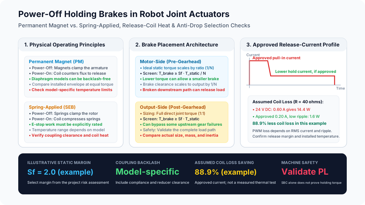
Power-Off Holding Brakes in Robot Joint Actuators: Permanent Magnet vs. Spring-Applied, Thermal Management, and Vertical-Axis Anti-Drop Sizing (2026)
Compare power-off holding brakes for robot joint actuators: PM vs spring-applied, thermal limits, and anti-drop sizing. Use the checklist to prepare your OEM RFQ.
Content reviewed: November 3, 2026. This guide is for robot OEM mechanical engineers, motion control engineers, and procurement teams worldwide selecting power-off holding brakes for robot joint actuators. It compares permanent magnet and spring-applied mechanisms, brake placement, thermal management, and vertical-axis anti-drop sizing.
Key Takeaways
- Hold and stop are separate requirements. A power-off brake applies without coil power, but its static holding rating does not establish dynamic stopping capacity or a safety performance level.
- Compare actual brake models. Permanent magnet (PM) diaphragm designs can provide backlash-free coupling. Spring-applied designs vary in backlash, package size, temperature limits, and permitted emergency-stop work; none of these is a universal property of the mechanism.
- Budget coil heat while the brake is released. Both conventional mechanisms need release power. Use the specified coil current and mounting conditions to calculate losses; an IP rating does not predict temperature rise.
- Reduce release power only with supplier approval. A pull-in stage followed by reduced current can save heat on compatible brakes. PWM duty cycle, boost duration, polarity, and release margin must match the exact brake and driver.
- Size the whole load path. A motor-side brake benefits from gear reduction but cannot restrain a load after a downstream coupling or reducer failure. Output-side restraint also needs an intact path to the load.
- Request evidence before approval. Obtain minimum holding torque at operating temperature and end of life, permitted friction work, engagement time with the actual suppression circuit, and a validated machine stopping sequence.
Preparing an RFQ? Use the sourcing checklist below to collect the brake and drive data before requesting an actuator quote.
The Role of Power-Off Brakes in Modern Robotics
For teams specifying integrated robot joint actuators, a motor torque rating alone does not answer what happens during a power loss. A gravity-loaded axis can move when drive torque disappears. Motor cogging, gear friction, and counterbalancing may affect that motion, but should not be credited as a protective holding function without validation.
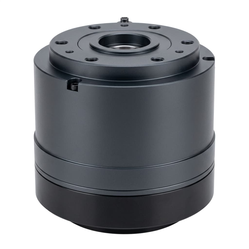
ISO 10218-1:2025 addresses industrial robot safety; the previously linked 2011 edition is withdrawn. The required safety functions and performance levels depend on the application risk assessment and applicable standards, including ISO 13849-1 where relevant. A brake component, Safe Brake Control (SBC) output, or two-brake arrangement alone does not establish machine compliance.
The engineering questions are practical:
- Which PM or spring-applied brake meets the axis holding, backlash, and emergency-stop requirements?
- Should it sit before the reducer or directly on the joint output?
- How much release-coil heat can the installed housing dissipate?
- How much movement occurs before and after the brake develops torque?
- What evidence and maintenance instructions must the supplier deliver?
Scope, Date, and Engineering Limits of This Guide
The review date is November 3, 2026. The mechanical discussion covers dry-friction electromagnetic holding brakes in articulated arms, collaborative robot joints, humanoid limbs, and vertical lifters. Their safety and regulatory requirements differ: ISO 10218-1:2025 excludes medical and healthcare robots and lifting or transporting people. Its industrial scope must not be extended to those applications.
Method and evidence: This is a component-selection framework based on manufacturer information and reproducible engineering arithmetic. The worked examples use explicitly assumed inputs; they are not measured actuator performance, customer results, or certification evidence. No brake endurance or sealed-joint thermal test is reported here.
Limits: Check the exact model's ambient and coil temperature limits, orientation, air gap, mounting surface, duty cycle, and dry-running requirements. The calculations do not qualify wet multi-disc brakes, pneumatic rod locks, cleanroom service, or radiation/high-temperature applications. Confirm regional legal requirements and machine-specific stopping behavior separately.
Operating Principles: Permanent Magnet vs. Spring-Applied Brakes
Conventional power-off PM and spring-applied brakes hold without electrical power and require coil power to release. Bistable or mechanically latched designs need a separate operating analysis.
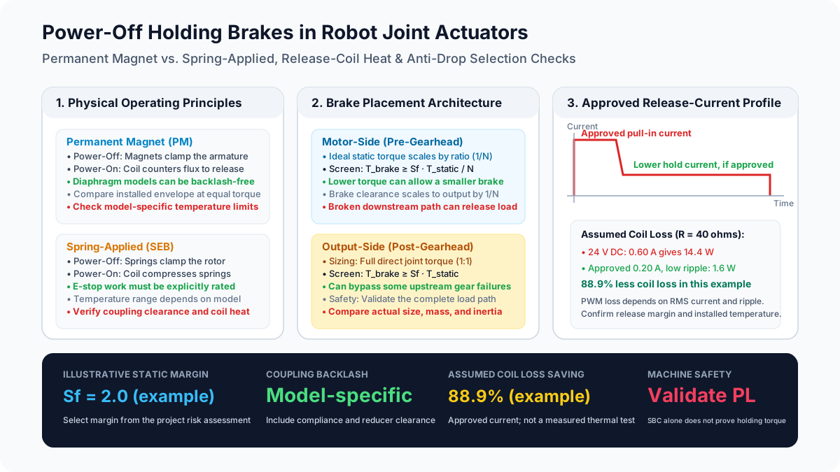
Conceptual selection diagram; numerical examples are assumptions, not product ratings or safety approvals.
1. Permanent Magnet (PM) Brakes
Permanent magnets attract an armature to the friction face when coil power is absent. During release, a correctly polarized coil creates an opposing field, allowing a spring element to retract the armature.
- Backlash: Some diaphragm-coupled PM designs have no geometric rotational clearance. This does not eliminate elastic deflection, mounting error, gearbox backlash, or whole-joint droop. KEB's brake portfolio identifies backlash-free PM models; verify the chosen model's drawing and torque-deflection behavior.
- Package: PM designs can suit compact servo joints, but compare the required torque, bore, inertia, and installed dimensions rather than assuming a torque-density advantage at every size.
- Temperature: Magnet grade, magnetic circuit, and coil temperature affect release and holding margins. There is no universal 100°C or 120°C demagnetization threshold for a complete PM brake.
- Supply: Use the specified polarity, voltage/current window, and hot/cold coil limits. Incorrect excitation can cause drag, incomplete release, heating, or magnet damage; a generic PWM setting is insufficient.
2. Spring-Applied Brakes
Mechanical springs clamp the friction member when power is removed. Energizing the coil attracts the armature and compresses the springs to release the rotor. Mayr's spring-applied brake overview describes this power-loss holding/stopping application and model-specific configurations.
- Backlash: Splined rotors may need clearance for axial sliding, while other coupling designs can reduce play. Request the actual angular clearance and stiffness; 0.5°–1.2° is not a valid family-wide specification.
- Dynamic capacity: Select a brake explicitly rated for the expected speed, friction work, and stop frequency. Spring application alone does not make a holding brake suitable for repeated dynamic braking.
- Temperature: Springs, linings, insulation, and clearances each have limits. Spring-applied construction does not establish a universal high-temperature rating.
- Release power: Calculate from the model's electrical data. Some compatible brakes allow reduced release current after pull-in; do not assume PM or spring-applied designs always consume less power than the other.
Architectural Placement: Motor-Side vs. Output-Flange Mounting
Brake position changes both torque demand and which mechanical failures the restraint can address.
| Architectural Parameter | Motor-Side Brake (Pre-Gearhead) | Output-Flange Brake (Post-Gearhead) | Engineering Impact & Procurement Decision |
|---|---|---|---|
| Torque requirement | Ideal static shaft demand is approximately load torque divided by reduction ratio | Must resist full joint load torque | Apply the selected margin to minimum guaranteed holding torque; verify the actual load path. |
| Package and mass | Lower shaft torque can permit a smaller brake | Higher torque can require a larger package | Compare installed dimensions and mass; no universal gram or kilogram range applies. |
| Backlash at the joint | Brake clearance is approximately divided by ratio; reducer clearance remains | Brake clearance acts directly at the output | Add compliance, mount movement, and reducer behavior to the droop budget. |
| Reducer failure | Cannot restrain the load if the downstream torque path breaks | Can bypass some upstream reducer failures | Confirm which shafts, bearings, fasteners, and housing parts remain in the holding path. |
| Dynamic energy | Sees high shaft speed and motor inertia plus reflected load inertia | Sees lower shaft speed and full output-side inertia | Reflect inertia consistently; moving the brake does not remove payload kinetic energy. |
| Integration | May share space with the motor and encoder | May surround the output bearing or flange | Check bore routing, runout, thermal path, contamination barriers, and service access. |
The Gearbox Failure Risk Dilemma
A motor-side brake can remain locked while a failed reducer or coupling releases the load. An output-side brake only helps if its own connection to the load and reaction structure remain intact.
Procurement rule: Select placement and any independent restraint from the machine risk assessment and credible failure modes. A dual-brake layout may improve redundancy, but common power, control, contamination, and structural failures still need analysis. Do not infer Category 4 or PL e from the number or location of brakes.
Thermal Management: Continuous Release Power & PWM Control
The brake is electrically energized while motion is permitted. Include this heat alongside motor, drive, and reducer losses when evaluating thermal derating in sealed robot joint actuators. Sealing alone does not determine a percentage loss of continuous torque.
Why Release Coils Add Heat
For steady DC current, resistive coil loss is:
P_coil = I² × R = V² / RAssumed example: A 24 V coil with resistance 40 ohms at the condition being analyzed draws 24 / 40 = 0.60 A and dissipates 14.4 W. Resistance changes with temperature. This calculation establishes electrical loss, not an 18°C–26°C temperature rise or a motor derating percentage. Those require the installed thermal path, duty cycle, ambient conditions, and measurement or a validated model.
Two-Stage Release Control
For a compatible spring-applied brake, an approved pull-in current can overcome the initial air gap; a lower current may then keep the armature released. A rated-voltage pull-in pulse is not itself overexcitation: that term applies when excitation exceeds the continuous rating. Use a boost only within the manufacturer's voltage, duration, and repetition limits.
PM flux-cancellation brakes need their own release-current window. Never transfer a spring-applied brake's reduced-current setting to a PM model without approval. The Synapticon documentation index is an entry point to product-specific drive manuals; it is not evidence that every drive supports the same PWM, suppression circuit, or safety function.
Conditional Power Savings Calculation
Suppose the brake manufacturer has approved 0.20 A as sufficient steady release current for the example coil, including hot/cold and supply tolerances:
P_hold = I_hold² × R = 0.20² × 40 = 1.6 W
Reduction = (14.4 - 1.6) / 14.4 × 100 = 88.9%
This is an illustrative DC/low-ripple result. For PWM, loss is I_rms² × R, including current ripple. A nominal one-third duty cycle can approximate 8 V average only under appropriate switching/freewheel conditions; it does not automatically produce 0.20 A or 1.6 W. A purely resistive chopped load would instead average D × V_bus² / R, or 4.8 W at one-third duty.
Procurement action: Request the approved pull-in and hold-current profiles, PWM compatibility, minimum release margin, suppression circuit, and measured coil/housing temperatures at worst-case duty. Continuous rated-voltage operation can be acceptable when the brake rating and installed thermal budget support it.
Comprehensive Comparison: PM vs. Spring-Applied Brakes in Robot Joints
Use this eight-row matrix to define evidence requirements rather than selecting from assumed family-wide ratings.
| Engineering Parameter | Permanent Magnet (PM) Brake | Spring-Applied Brake | Selection Guidelines for Robot Builders |
|---|---|---|---|
| Engagement mechanism | Permanent magnet attraction | Mechanical spring force | Both conventional types apply on loss of release power. |
| Mechanical backlash | Diaphragm models can be backlash-free | Depends on rotor/hub coupling; reduced-play designs exist | Request clearance and torsional stiffness at the specified torque. |
| Torque density and profile | Compact servo designs available | Compact servo designs also available | Compare drawings at equal guaranteed torque and temperature. |
| Continuous release power | Coil counters magnet attraction | Coil holds armature against springs | Obtain actual hot/cold current and rated duty. |
| Reduced-current operation | Requires approved flux-cancellation window | Often possible on compatible designs | Confirm brake/driver compatibility before specifying PWM. |
| Temperature sensitivity | Magnet grade, coil, friction, and gap matter | Springs, coil, friction, and gap matter | Request minimum torque and reliable release across the full operating range. |
| Dynamic stopping | Only within the chosen model's rating | Only within the chosen model's rating | Require speed, energy per stop, cumulative work, and stop-frequency limits. |
| Supply tolerance | Observe polarity and release-current window | Observe pull-in/hold and thermal limits | Validate bus extremes, wiring drop, suppression, and fault response. |
Dynamic Sizing & Mathematical Calculations
Separate static holding, dynamic stopping, and movement during engagement delay. Passing one check does not establish the others.
1. Static Holding Torque Calculation
For the illustrated horizontal cantilever pose, gravity torque is:
T_static = m_arm × g × L_com + m_payload × g × L_payloadHere masses are in kg, perpendicular lever arms in m, and g = 9.81 m/s². Evaluate all poses, downstream links, tooling, payload offsets, and external loads. For a motor-side brake with reduction ratio N = motor speed / output speed, an ideal preliminary screen that takes no credit for gearbox friction is:
T_brake_required = S_f × T_static / N
T_output_brake_required = S_f × T_static
A running gearbox efficiency is not a static safety factor. Verify backdriving behavior and the actual torque transmission path with the reducer supplier. Apply the selected margin to the brake's minimum guaranteed torque under the required temperature, wear, installation, and environmental conditions.
Worked example, not a product rating: Assume a 4 kg downstream assembly at 0.25 m, a 5 kg payload at 0.40 m, ratio N = 80, and an illustrative margin S_f = 2.0:
T_static = 4 × 9.81 × 0.25 + 5 × 9.81 × 0.40 = 29.43 Nm
Motor-side requirement = 2.0 × 29.43 / 80 = 0.736 Nm
Output-side requirement = 2.0 × 29.43 = 58.86 Nm
The margin of 2.0 is an assumption for this example, not a universal standards requirement or proof of safety. Select the project margin from the risk assessment and supplier method. Grease contamination is a fault to prevent and evaluate; a larger nominal torque does not automatically make contaminated friction surfaces acceptable.
2. Dynamic Emergency-Stop Energy Calculation
If the holding brake must stop a moving axis after loss of drive torque, the manufacturer must permit that use. For motor-side calculations, reference every inertia to the brake shaft:
J_total = J_motor + J_brake + J_gear_ref + J_load / N²
E_k = 0.5 × J_total × omega_m²
W_stop = E_k + W_gravity + W_other - W_other_dissipation
J_gear_ref is gearbox inertia already referred to the motor shaft; do not divide it by N² again. omega_m is speed when effective braking starts, including any speed increase during engagement delay. Gravity work is the integral of gravity torque over the joint output angle during braking; for a small interval with approximately constant torque, W_gravity ≈ T_static × delta_theta_joint.
For an assumed J_total = 0.0002 kg·m², omega_m = 100 rad/s, T_static = 29.43 Nm, and downward braking travel delta_theta_joint = 0.01 rad, neglecting other work and losses:
E_k = 0.5 × 0.0002 × 100² = 1.0 J
W_gravity = 29.43 × 0.01 = 0.2943 J
W_stop ≈ 1.2943 J
The assumed angle must subsequently be checked against available dynamic torque and actual stopping behavior. Compare the result with permitted work per stop at the relevant speed and temperature, cumulative work, repetition rate, and wear limits. Energy alone cannot verify deceleration or stopping distance. Do not assume a universal 50–500-stop lifetime or calculate a service life simply by dividing total energy by one stop's energy.
3. Brake Response Timing & Gravity Drop Distance
Coil-current decay, armature travel, and torque build-up take time. A recirculating diode can slow current decay; faster suppression changes transistor voltage stress and must match the brake and driver ratings. Use measured or guaranteed time to useful torque with the actual installed circuit, not a universal 10 ms or 20 ms requirement.
For a simplified unrestrained translating load, constant downward acceleration during a delay gives:
h_delay = v_0 × t_delay + 0.5 × a_drop × t_delay²With assumed v_0 = 1.0 m/s, t_delay = 0.060 s, and a_drop = 9.81 m/s², h_delay = 0.077658 m, or 77.7 mm before effective braking. Even a 20 ms delay would give about 22.0 mm under these assumptions, before adding braking travel.
This free-translation example is not a robot TCP drop prediction or a guaranteed bound. A rotating arm requires its inertia, pose-dependent gravity torque, reducer behavior, residual drive torque, backlash, and kinematics. Include motion during torque build-up and subsequent deceleration in the full stopping-distance validation. During a planned stop, confirm the brake's holding action before removing motor support according to the validated control sequence.
Contamination & Encoder Protection: Brake Dust
In compact integrated joint actuators, the brake and encoder may share a housing. Frictional engagement, particularly dynamic stopping or unintended drag, can create wear debris. Optical sensing surfaces can be obscured, and magnetic debris near magnetic encoders can disturb sensing; the severity depends on the encoder and enclosure design.
When reviewing the design:
- Separate friction and sensing spaces where needed. Ask for the barrier, sealing, and contamination-control details, not just an external IP rating.
- Check lubricant migration. Gear grease on dry-friction faces can compromise torque and requires a defined fault response and service procedure.
- Verify cleanliness requirements. Neither PM nor spring-applied friction brakes are inherently wear-free or cleanroom-qualified. Request particle data and application-specific evidence where cleanliness matters.
- Confirm maintenance access. Obtain air-gap, wear, inspection, replacement, and post-emergency-stop instructions for the selected model.
The OEM Actuator Brake Sourcing Checklist
Before approving a drawing or issuing a purchase order, obtain these answers in writing:
- 1. Holding torque and load path: Worst-case pose, tooling, payload, external loads, ratio, selected margin, and minimum guaranteed hot/end-of-life brake torque are documented.
- 2. Mechanism and backlash: The exact PM or spring-applied model, angular clearance, torsional stiffness, bore, and installed envelope are identified.
- 3. Supply and release margin: Polarity, bus extremes, cable voltage drop, coil resistance/current, and hot/cold pull-in and release limits are confirmed.
- 4. Thermal and PWM compatibility: Any pull-in boost or reduced hold current has written brake/driver approval; installed temperature and duty-cycle limits are verified.
- 5. Engagement timing: The actual suppression circuit, voltage stress, detection/control delays, torque build-up, and complete stopping movement are validated.
- 6. Dynamic work and maintenance: Allowed speed, torque, work per stop, cumulative work, repetition rate, inspection, and replacement criteria are supplied.
- 7. Contamination and structural faults: Lubricant migration, brake debris, encoder isolation, reducer/coupling failure, and any independent restraint are evaluated.
- 8. Safety function evidence: Required performance level, brake-control architecture, diagnostics/test coverage, fault response, and machine validation responsibility are assigned. SBC controls brake actuation; it does not measure mechanical holding torque by itself.
Frequently Asked Questions (FAQ)
Q1: Can a power-off holding brake stop the robot during normal operational cycles?
Use the drive for planned deceleration and apply the holding brake according to the approved sequence. Use a mechanical brake for routine dynamic stopping only if that specific model and system are rated for it. Emergency-use friction-work allowance does not establish a routine stopping duty.
Q2: Why does a joint move when its brake engages?
Possible contributors include current-decay delay, armature movement, torque build-up, brake/reducer clearance, elastic deflection, insufficient torque, and contamination. Measure the complete sequence with the actual payload and temperature. Do not diagnose a flyback diode or brake fault solely from observed tool movement.
Q3: How does temperature affect PM holding brakes?
Temperature changes magnet behavior, coil resistance, and the release/holding margins. Magnet flux percentage loss cannot be translated directly into the same percentage holding-torque loss. Request model-specific minimum torque and release limits across the operating range; generic magnet temperature coefficients are insufficient.
Q4: Can I buy a joint actuator without a brake to save weight and cost?
Possibly, if the machine's risk assessment and validated measures allow it. A vertical-axis motor may be unloaded by a counterbalance, and a nominally horizontal axis may still need restraint for external forces or process hazards. Axis number alone does not decide the brake requirement. Confirm the proposed restraint and fault behavior before omitting it.
Q5: What is a Safe Brake Test (SBT)?
An SBT checks a brake's ability to hold a defined test torque while monitoring movement under controlled conditions. Test torque, interval, detection threshold, and load protection must follow the safety design and component instructions. A generic 1.3× torque or shift-start test is not universally mandated. Diagnostic coverage and machine validation determine what safety credit the test provides.
Q6: What is the difference between Category 0 and Category 1 stops?
Category 0 removes power to the actuators immediately; Category 1 retains power for a controlled stop and removes it afterwards. An emergency-stop function does not always mean Category 0. A physical brake still has engagement delay, and the selected safety architecture determines the sequence. Safe Stop 1 and Safe Brake Control need appropriate implementation and validation; these labels alone do not prove the load is held.
Next Steps & Technical Sourcing Alignment
Bring the load case, thermal duty, permitted movement, and required fault response into the same RFQ. A quote listing only nominal holding torque leaves key selection questions unanswered.
- Compare the Integrated Harmonic Joint Actuator family and request the exact proposed brake and driver data.
- Review High-Torque Cycloidal Joint Actuators for heavier loads; confirm brake mechanism and emergency-stop ratings for the quoted configuration.
- Check Crossed Roller Bearings in Robot Joints for output moment rigidity and flange-load considerations.
- For a configuration review, send a technical inquiry and RFQ with worst-case gravity torque, ratio, speed/inertia, bus voltage, ambient/coil temperatures, duty cycle, acceptable drop, and required safety functions. Request model-specific evidence before design approval.
Sources and References
Sources reviewed November 3, 2026. Manufacturer overview pages establish mechanism and product-family context; obtain the exact model manual and safety documentation for numerical limits. They do not substantiate the assumed examples above.
- Mayr — Spring-applied brakes / safety brakes. Manufacturer overview of power-loss braking, configurations, and supply modules. The legacy URL redirects to its spring-applied brake glossary; it is not a ROBA-servostop model datasheet.
- KEB Automation — Brakes and clutches. Lists spring-applied and PM families, including backlash-free PM models. This is a product portfolio, not a comparative thermal test or white paper.
- Synapticon — Documentation index. Redirects to the manufacturer's documentation portal. Select the actual drive and firmware manual to confirm brake-control capabilities; the index provides no universal PWM settings or SBC approval.
- ISO 10218-1:2025 — Robotics safety requirements, industrial robots. Official edition and scope record. This replaces the withdrawn 2011 reference; the public summary does not establish a particular PL, brake arrangement, test interval, or machine compliance.
Author

Categories
More Posts
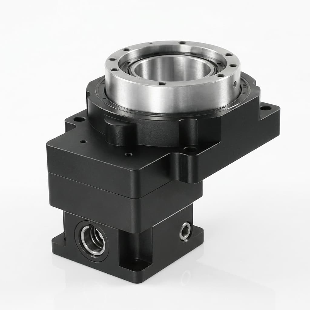
Strain Wave vs Cycloidal Drives in Robot Joints: Precision vs Robustness
Compare strain wave and cycloidal drives for robot joint actuators by backlash, shock load, torque density, cost, service life, and RFQ fit before sourcing.
Robot Joint Actuator RFQ Template: 25 Fields Buyers Should Send
A buyer-grade RFQ template with 25 mandatory fields, supplier red flag checklist, complete fill-in example, quote-comparison matrix, and timeline expectations to reduce rework and speed supplier evaluation.
Crossed Roller Bearings in Robot Joint Flanges: Tilting Moment Rigidity, Runout Tolerances, and Overhung Load Sizing
Size crossed roller bearings for robot joint actuators: compare moment rigidity, runout, preload, and overhung loads. Use the engineering checklist for an RFQ.