Crossed Roller Bearings in Robot Joint Flanges: Tilting Moment Rigidity, Runout Tolerances, and Overhung Load Sizing
Size crossed roller bearings for robot joint actuators: compare moment rigidity, runout, preload, and overhung loads. Use the engineering checklist for an RFQ.
Content reviewed: October 30, 2026. This guide is written for robot OEM mechanical engineers, motion control architects, and B2B procurement leads specifying output flange bearings for articulated robot arms, collaborative robots (cobots), SCARA systems, and humanoid joint modules globally.
When sizing crossed roller bearings for robot joint actuators, check output torque, reduction ratio, and motor power alongside the output bearing's tilting moment capacity and rigidity. Adequate motor torque does not establish that a flange can support a cantilevered payload within its tool center point (TCP) error budget.
This guide provides reproducible engineering formulas, bearing comparisons, a runout acceptance matrix, and an 8-point procurement checklist. Examples use hypothetical inputs, not measured product performance. They support preliminary sizing of low-speed rotary joints; supplier calculations and mounted qualification are still required for shocks, oscillation, temperature extremes, and safety-critical applications.
Preparing a bearing specification? Use the Robot Joint Actuator RFQ Template to record the load cases and acceptance evidence below.
Key Takeaways
- Size overhung moment explicitly: A 12 kg payload at 750 mm produces 88.3 Nm under gravity, or 132.4 Nm at a total effective transverse acceleration of 1.5g. An upward acceleration of 1.5g in addition to gravity instead produces 220.7 Nm. State which load case applies.
- Compare mounted rigidity: Roller line contact can provide a compact, stiff arrangement, but the advantage over a ball-bearing pair depends on diameter, preload, support spacing, and housing stiffness. Request comparable moment-versus-tilt curves.
- Allocate a flange-tilt budget: Bearing deflection contributes to TCP error and interface misalignment. There is no universal allowable tilt angle for all strain wave or cycloidal reducers.
- Balance preload against friction: More preload can increase stiffness and drag. Clearance codes and permissible starting torque are specific to each supplier and frame size.
- Check thermal fit changes: Aluminum and steel expand differently. Evaluate the assembled bearing at both temperature extremes rather than relying on a room-temperature fit.
- Quote the complete mounting arrangement: Compare split-ring and integrated mounting-hole designs using bearing cost, housing machining, assembly, inspection, and rework costs; savings require actual quotations and process data.
1. The Core Mechanical Dilemma: Why Joint Actuators Fail Under Cantilevered Moments
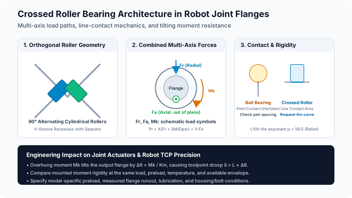
In multi-axis serial robotic manipulators, joint actuators do not operate in pure torsion. While the motor rotor supplies rotary torque about the central axis (Z), the output flange is subjected to simultaneous multidirectional forces:
- Radial shear force (
F_r): Generated by arm weight, transverse tool acceleration, and side-thrust during process tasks such as grinding, polishing, or insertion. - Axial thrust force (
F_a): Generated by vertical payload gravity, plunge drilling, or pushing forces along the joint centerline. - Overhung tilting moment (
M_k): Generated whenever a radial force or axial force acts at an offset lever distance (L) from the center plane of the output bearing.
M_k = sum of transverse force × lever arm for a coplanar load case
General case: M = sum(r_i × F_i); resolve the components perpendicular to joint axis Z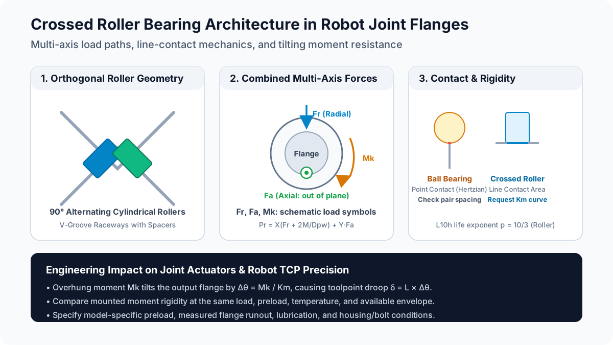
The Mechanics of Angular Flange Tilt and TCP Droop
When a joint actuator encounters a tilting moment M_k, the output flange tilts relative to the stationary actuator housing by an angular displacement Δθ_f:
Δθ_f = M_k / K_mUse consistent units: convert K_m from kNm/rad to Nm/rad before dividing a moment in Nm, and use radians in the TCP displacement equation.
Where:
Δθ_f: Angular flange tilt (rad or arcmin)M_k: Applied tilting moment (Nm)K_m: Bearing tilting moment rigidity (kNm/radorNm/arcmin)
This angular deflection is mechanical and downstream of the motor rotor. If the robot arm extends an effective reach L_arm from the tilted joint to the end-effector tool center point (TCP), the tangential position droop (δ_TCP) at the tool tip is:
δ_TCP ≈ L_arm × Δθ_f = L_arm × (M_k / K_m)Worked Sizing Example: Cantilevered Arm Deflection
Consider a collaborative robot elbow joint (Axis 3) operating under the following parameters:
- Cantilevered reach from Axis 3 to end-effector (
L_arm):0.75 m(750 mm) - Total payload plus tooling mass (
m):12 kg - Total effective transverse acceleration (
a):1.5g(14.715 m/s^2, usingg = 9.81 m/s^2), including gravity as resolved in this simplified posture - Effective dynamic payload force:
F_dyn = 12 × 14.715 = 176.58 N - Applied dynamic tilting moment:
M_k = 176.58 N × 0.75 m = 132.435 Nm ≈ 132.4 Nm
Now compare two hypothetical bearing arrangements supporting Axis 3. The stiffness inputs are illustrative, not catalogue ratings or a controlled comparison at identical dimensions. Link self-weight, process forces, and other joints are excluded here.
-
Option A: Duplex Angular Contact Ball Bearing Set
- Tilting moment rigidity:
K_m = 65 kNm/rad = 65,000 Nm/rad(18.9 Nm/arcmin) - Angular flange tilt:
Δθ_f = 132.435 / 65,000 ≈ 0.002037 rad ≈ 7.00 arcmin - Tangential TCP droop:
δ_TCP = 0.75 m × 0.002037 rad ≈ 0.00153 m = 1.53 mm
- Tilting moment rigidity:
-
Option B: Precision Crossed Roller Bearing (CRB)
- Tilting moment rigidity:
K_m = 240 kNm/rad = 240,000 Nm/rad(69.8 Nm/arcmin) - Angular flange tilt:
Δθ_f = 132.435 / 240,000 ≈ 0.000552 rad ≈ 1.90 arcmin - Tangential TCP droop:
δ_TCP = 0.75 m × 0.000552 rad ≈ 0.000414 m = 0.41 mm
- Tilting moment rigidity:
The engineering implication: These assumed stiffness values reduce the bearing-only TCP deflection by approximately 73% (from 1.53 mm to 0.41 mm). This is an arithmetic comparison, not a guaranteed improvement from changing bearing type. For a 0.10 mm bearing-only TCP allowance at 132.435 Nm and 0.75 m reach, the required stiffness is K_m ≥ M_k × L_arm / δ_TCP = 993,262.5 Nm/rad. Housing and link compliance consume additional error budget. A motor-side encoder does not directly measure this flange tilt; output sensing and compensation still require structural validation.
Internal Reducer Protection: Preventing Flexspline Tooth Edge Loading
Check how the output bearing arrangement controls misalignment at the reducer interface:
- In strain wave (harmonic) reducers, verify the permitted output interface misalignment and how external loads reach the flexspline assembly.
- In cycloidal reducers, verify the output bearing arrangement and the allowable external moment at the specified duty cycle. Some reducers already incorporate substantial output support.
A correctly designed bearing and housing provide a load path into the robot link. They do not automatically isolate the gear mesh from all bending; confirm the assembled load path and interface limits with the reducer supplier.
2. Contact Mechanics: Crossed Roller Bearings vs. Alternative Bearing Architectures
Compare rolling-element contact geometry alongside the complete bearing arrangement:
Line Contact vs. Point Contact Mechanics
- Ball bearings: Ball-to-raceway contact forms a loaded elliptical area. A back-to-back angular contact pair can achieve substantial moment stiffness through its contact angle, preload, and support spacing.
- Crossed roller bearings: Cylindrical rollers provide nominal line contact. THK's product overview describes high rigidity in a compact envelope. Its comparison with conventional thin angular ball bearings is not a universal multiplier for every duplex bearing arrangement.
90° Orthogonal Roller Kinematics
In a crossed roller bearing, adjacent roller axes alternate by 90° in a V-groove track. Opposing orientations support axial loads in both directions; the rollers around the circumference collectively react radial and moment loads. A roller set cannot be assigned a universal positive or negative radial-load direction independently of its circumferential position.
Separators between adjacent rollers reduce roller-to-roller friction and skewing. This configuration allows a single bearing assembly to support combined loads in a compact envelope; confirm whether the selected model uses separators, a cage, or a full-complement arrangement.
Comprehensive Comparison: Output Bearing Architectures in Robotics
The table below compares the three primary bearing architectures evaluated by robot actuator design teams:
| Engineering & Procurement Dimension | Crossed Roller Bearing (CRB) | Duplex Angular Contact Ball Bearings (DF / DB) | Four-Point Contact Ball Bearing (Thin-Section) |
|---|---|---|---|
| Contact Geometry | Line contact along 90° alternating cylindrical rollers | Point contact along paired raceway grooves | 4-point Gothic arch point contact on single row of balls |
Tilting Moment Rigidity (K_m) | Request mounted moment-versus-tilt curve | Compare DF/DB configuration, preload, and support spacing | Verify moment stiffness for the selected section and preload |
| Axial Package Envelope Height | Single ring; compare actual catalogue dimensions | Two bearings and any spacers or retainers | Single ring; compare section size and retention |
Combined Load Capacity (F_r, F_a, M_k) | Check catalogue equivalent loads and static limits | Calculate load sharing between both bearings | Check combined-load limits for the chosen contact geometry |
No-Load Starting Friction Torque (T_0) | Measure with specified preload, grease, and seals | Measure the complete mounted pair | Measure under the same temperature and sealing conditions |
| Limiting Operating Speed | Use the selected model's speed and lubrication limits | Evaluate speed, preload, and thermal growth together | Use the selected model's speed and combined-load limits |
| Sensitivity to Housing Bore Geometry | Check thin-ring distortion and clamp uniformity | Check shaft/housing fits and alignment | Check thin-ring support and raceway distortion |
| Assembly & Shimming Complexity | Mounting holes may simplify retention; split rings need controlled clamping | Control pair orientation, spacing, and preload | Control retention and mounting flatness |
| Installed Cost Evidence | Quote bearing, housing, fasteners, assembly, and inspection | Include both bearings, spacers, machining, and inspection | Include retention hardware and inspection |
| Selection Trigger | Compact joint with combined loads and a tight tilt budget | Space available for a supported pair or speed-driven design | Compact arrangement whose verified load and stiffness ratings suffice |
3. Engineering Sizing Equations: Dynamic Equivalent Load & ISO 281 Life Rating
To prevent premature bearing spalling or catastrophic brinelling, procurement teams must verify that actuator suppliers have sized the output bearing according to recognized international standards (ISO 281 and manufacturer-validated kinematics).
The Dynamic Equivalent Radial Load Formula
When a crossed roller bearing is subjected to concurrent radial load (F_r), axial load (F_a), and tilting moment (M_k), the combined stress field is converted into an equivalent dynamic radial load (P_r):
P_r = X × (F_r + (2 × M_k) / D_pw) + Y × F_aWhere:
P_r: Dynamic equivalent radial load (N)F_r: Applied dynamic radial force (N)F_a: Applied dynamic axial force (N)M_k: Applied dynamic tilting moment (N·mm) (Note: ConvertNmtoN·mmby multiplying by1,000)D_pw: Pitch circle diameter of the rollers (mm), approximated for this catalogue method as:
D_pw ≈ (d_inner + D_outer) / 2X: Dynamic radial load factorY: Dynamic axial load factor
Standard Piecewise Factor Boundaries
The following factors follow IKO's catalogue, equations (1) and (2) and Table 5, printed page J7. Apply them only where the chosen manufacturer's calculation method agrees; use the actual roller pitch diameter when supplied.
-
When
F_a / (F_r + 2M_k / D_pw) ≤ 1.5(Moment- & Radial-Dominant Regime):X = 1.0Y = 0.45
-
When
F_a / (F_r + 2M_k / D_pw) > 1.5(Thrust-Dominant Regime):X = 0.67Y = 0.67
Static Safety Factor Calculation (f_s)
Before verifying dynamic fatigue life, engineers must check against permanent plastic brinelling under peak emergency stop or collision conditions:
P_0 = F_r + (2 × M_k) / D_pw + 0.44 × F_a
f_s = C_0 / P_0
Where:
P_0: Static equivalent radial load (N)C_0: Basic static load rating from manufacturer datasheet (N)f_s: Static safety factor
Design boundary: Calculate this ratio with peak loads, including relevant emergency stops, and agree the required safety factor with the bearing supplier. A project screening threshold such as f_s ≥ 3 is an assumption, not a universal robot or human-safety requirement. Static capacity does not establish rigidity or fatigue life.
ISO 281 Rating Life Equation for Cylindrical Rollers
Unlike ball bearings which utilize a cubic life exponent (p = 3), crossed roller bearings utilize an exponent of p = 10/3 ≈ 3.333 reflecting line contact stress distribution:
L_10 = ( C / (f_w × P_r) )^(10/3) × 10^6 revolutionsTo convert rating life into operating service hours (L_10h):
L_10h = ( 10^6 / (60 × n_m) ) × ( C / (f_w × P_r) )^(10/3) hoursWhere:
L_10h: Basic rating life at 90% reliability (hours)C: Basic dynamic load rating (N)n_m: Constant rotational speed of the joint flange (RPM) for this simplified calculationf_w: Application service load factor:1.0–1.2: Smooth motion, vibration-free laboratory automation1.2–1.5: Illustrative normal-motion screening range1.5–3.0: Heavy duty cycle, shock loads, milling/machining end-effectors
These basic rating-life equations use a one-million-revolution dynamic-rating basis and assume adequate lubrication, mounting, and operating conditions. Confirm the catalogue's rating basis and any temperature or preload corrections. For variable loads, accumulate damage over the load/speed spectrum; an arithmetic mean speed and a single worst-case posture do not establish actual service life. Small-angle oscillation needs separate supplier assessment.
Step-by-Step Worked Sizing Calculation
Evaluate a hypothetical output bearing at a constant load and speed. The capacities below are assumed inputs, not the specification of a Size 25 actuator or an identified commercial bearing:
- Actuator Bearing Pitch Diameter (
D_pw):115 mm - Basic Dynamic Load Rating (
C):32,500 N(32.5 kN) - Basic Static Load Rating (
C_0):48,000 N(48.0 kN) - Applied External Loads under Worst-Case Dynamic Posture:
- Dynamic Radial Force (
F_r):650 N - Dynamic Axial Thrust (
F_a):450 N - Cantilevered Tilting Moment (
M_k):160 Nm = 160,000 N·mm - Constant Joint Speed (
n_m):25 RPM - Service Factor (
f_w):1.35
- Dynamic Radial Force (
Step 1: Calculate Equivalent Moment Load Term
(2 × M_k) / D_pw = (2 × 160,000 N·mm) / 115 mm = 2,782.6 NNotice that the tilting moment contributes 2,782.6 N of equivalent radial load—over four times greater than the direct radial load (650 N)!
Step 2: Determine Load Factor Regime
Denominator = F_r + (2 × M_k) / D_pw = 650 + 2,782.6 = 3,432.6 N
Load Ratio = F_a / Denominator = 450 / 3,432.6 = 0.131
Because 0.131 ≤ 1.5, we apply X = 1.0 and Y = 0.45.
Step 3: Calculate Dynamic Equivalent Radial Load (P_r)
P_r = 1.0 × 3,432.6 + 0.45 × 450 = 3,432.6 + 202.5 = 3,635.1 NStep 4: Verify Static Safety Factor (f_s)
P_0 = 3,432.6 + 0.44 × 450 = 3,630.6 N
f_s = C_0 / P_0 = 48,000 / 3,630.6 = 13.22 (above this example's screening threshold of 3)
Step 5: Calculate Basic Rating Life (L_10h)
Effective dynamic load = f_w × P_r = 1.35 × 3,635.1 N = 4,907.4 N
Load Ratio (C / (f_w × P_r)) = 32,500 / 4,907.4 ≈ 6.6226

(6.6226)^(10/3) ≈ 545.5

L_10 ≈ 545.5 × 10^6 revolutions
L_10h ≈ (1,000,000 / 1,500) × 545.5 ≈ 364,000 hours (rounded)
This is a basic fatigue-rating result at 90% reliability, not a maintenance interval, measured service life, or actuator lifetime guarantee. As a separate constant-load sensitivity case, doubling the moment to 320 Nm while keeping other inputs unchanged gives P_r = 6,417.7 N and L_10h ≈ 54,700 hours, about an 85% reduction. A single collision cannot be represented as a permanently doubled fatigue load; assess its peak static load and possible damage separately.
4. Precision Grades and Flange Runout Tolerances
Bearing accuracy class and assembled flange runout are different acceptance requirements. ISO 492:2023 covers dimensional and geometrical tolerances for radial rolling bearings; it does not establish the TCP accuracy of a complete robot. Confirm which standard, edition, and manufacturer's accuracy table apply to the selected crossed roller bearing.
Critical Runout Definitions
- Inner-ring radial runout (
K_ia) and outer-ring radial runout (K_ea): Identify the rotating ring and the catalogue's measurement definition. - Axial running accuracy: Ask for the manufacturer's applicable symbols, reference surfaces, and measurement procedure. A bearing-ring measurement is not automatically an inspection of the robot's output flange.
- Assembled flange face runout: Specify total indicator reading (TIR), gauge radius or diameter, datum axis, applied measurement load, temperature, and bolt condition.
- Elastic tilt under load: Specify moment versus angular displacement separately. Unloaded runout does not establish loaded moment rigidity.
Precision and Inspection Acceptance Matrix
Use this matrix in an RFQ rather than assigning one micron limit to every bearing from 80 to 180 mm. It is an acceptance-planning worksheet, not an ISO tolerance table.
| Requirement | What the buyer supplies | What the supplier must return |
|---|---|---|
| Accuracy class | Candidate class, such as P5 or P4, and exact bearing model | Applicable standard/edition, size interval, and catalogue table |
| Inner-ring radial runout | Rotating ring, datum, and allowed radial error | Applicable K_ia limit and inspection record |
| Outer-ring radial runout | Whether the outer ring rotates and the housing reference | Applicable K_ea limit and inspection record |
| Axial running accuracy | Reference face and axial error allocation | Model-specific tolerance, symbol, and measurement method |
| Mounted flange face TIR | Gauge diameter, bolt torque, temperature, and TIR limit | Assembly inspection at those same conditions |
| Moment rigidity | Operating moment and permitted flange tilt | Mounted moment-versus-tilt curve, preload, and test setup |
| Thermal repeatability | Cold/hot operating conditions and allowable drift | Repeat measurements after agreed thermal cycles |
| Measurement capability | Datum scheme, sampling plan, and acceptance rule | Gauge uncertainty and traceable inspection report |
Selection rule: Derive limits from the robot's error budget, then compare quotations for the classes that meet them. P2, SP, and vendor-specific grades are not interchangeable labels. Neither P5 nor P4 alone guarantees a particular robot repeatability or application suitability.
As an illustrative geometry check, 5 μm face TIR measured over a 100 mm gauge diameter corresponds to about 50 μrad of tilt if all TIR comes from planar tilt. At 750 mm reach, that contributes about 0.0375 mm of lateral displacement. Surface waviness, radial error, and loaded elastic deflection require separate allowances.
5. Preload Selection, Friction, and Thermal Fit
Preload reduces internal clearance by introducing contact load before the external working load is applied. It can improve stiffness while increasing friction and sensitivity to mounting distortion.
Preload Codes Are Supplier-Specific
Positive clearance, near-zero clearance, and preloaded variants can all appear in product catalogues. Codes such as T1, C1, T2, or VSP must be interpreted using the selected manufacturer's series and size table. Do not transfer a code or a negative-clearance value between brands.
Ask for both starting torque and running torque with the specified grease, seals, temperature, and mounting condition. Starting torque alone does not quantify continuous heating. At constant speed, frictional power can be estimated from measured running torque:
P_friction [W] = T_running [Nm] × 2π × n [rpm] / 60For an assumed running torque of 0.5 Nm at 25 rpm, the represented bearing and seal drag dissipates approximately 1.31 W. This is a calculation example, not a measurement. Add motor and reducer losses when assessing the complete joint's thermal budget.
Check the Assembled Thermal Behavior
An IP65/IP67 enclosure rating does not specify bearing temperature or permitted preload. Ring temperatures, housing fits, grease, and heat flow determine whether preload rises or relaxes as the joint warms. Qualify the assembled joint over its actual duty cycle; do not assume a universal thermal-runaway threshold or select grease solely from a nominal temperature rating.
Housing Differential Thermal Expansion: Steel vs. Aluminum
For an illustrative fit calculation, assume a steel ring coefficient of 11.7 × 10^-6/K, an aluminum housing coefficient of 23.0 × 10^-6/K, and equal uniform temperature rise of 40 K at a 120 mm bore. Confirm actual alloy data and temperatures before using this calculation in a design.
ΔD_alum = 120 mm × 23.0 × 10^-6/K × 40 K = 0.1104 mm
ΔD_steel = 120 mm × 11.7 × 10^-6/K × 40 K = 0.0562 mm
Differential free expansion ≈ 0.0542 mm = 54.2 μm
This differential could consume an assumed 10–20 μm interference. It does not prove that every mounted ring will creep: constraint, retention, and unequal temperatures change the result. Evaluate steel inserts or an engineered flange retention arrangement where appropriate. Bolting a flange does not remove differential expansion; the supplier must validate contact, fastener preload, housing distortion, and runout through thermal cycling.
6. Mechanical Packaging & Mounting: Integrated Flange vs. Split-Ring Topology
Compare the complete mounting arrangement, not just the bearing purchase price. THK's product overview distinguishes separable-ring and integrated-ring designs; confirm the exact model drawing before specifying retention hardware.
Split-Ring Design
A split-ring design needs controlled housing support and clamping. Bore form error, cover-plate stiffness, or uneven bolt torque can distort a thin ring and increase friction. Request the manufacturer's fit, shoulder dimensions, mounting sequence, and post-assembly inspection procedure.
Integrated Mounting-Hole Design
Designs such as IKO CRBF and THK RU provide mounting interfaces that may simplify assembly. Check which holes are threaded or through holes, which ring rotates, and the specified mounting-face flatness. Solid rings still depend on proper housing support and bolt tightening.
Quote Total Installed Cost
Installed cost = bearing + housing machining + retention hardware
               + assembly labor + inspection + expected rework
Ask suppliers to itemize these terms at the same annual quantity and accuracy requirement. No universal component price, assembly-time saving, or warranty reduction follows from choosing an integrated flange.
For a comparable quotation, transfer the selected load cases and inspection conditions to the RFQ template.
7. The OEM Procurement & RFQ Technical Acceptance Checklist
Replace a generic requirement such as “high rigidity bearing” with evidence that can be reviewed and inspected:
- 1. Load cases and capacity: Provide radial force, axial force, tilting moment, speed, acceleration, emergency-stop loads, and duty cycle. Request static and dynamic calculations, the chosen safety factor, and a mounted rigidity curve.
- 2. Running accuracy: Identify the exact bearing model, rotating ring, accuracy class, applicable standard, and runout limits. Request a pilot-batch inspection report and a separate mounted flange TIR result.
- 3. Preload and friction: Record the supplier's preload/clearance code and actual limits. Agree maximum starting and running torque at defined temperature, grease, seals, and mounting conditions.
- 4. Mounting interface: Specify integrated or split-ring construction, mounting-face datums, fits, bolt sizes and tightening sequence. Use the bearing manufacturer's drawing rather than a universal H7/h6 fit.
- 5. Thermal fit: Supply minimum and maximum operating temperatures and housing material. Request the thermal-fit assessment and allowable hot/cold runout and torque drift.
- 6. Lubrication: Confirm approved grease or oil, fill quantity, relubrication interval, seal compatibility, and oscillation suitability. State food-contact or vacuum requirements when applicable; a grease designation alone does not qualify the whole joint.
- 7. Seal and friction budget: Include seal drag in the no-load torque and running-loss budget. Agree cold-start and warm-running measurement conditions for the complete actuator.
- 8. Qualification and traceability: Agree a representative loaded duty-cycle test, ambient conditions, duration, sampling, and acceptance limits for temperature, friction, runout, and tilt. Require bearing identity and inspection records; a generic 100-hour test is not universal qualification.
8. Frequently Asked Questions (FAQ)
Q1: Why not simply increase the size of the strain wave gearbox instead of upgrading the bearing?
A: Gear torque capacity and output-bearing moment capacity are separate checks. Upsizing can help if the larger unit also has suitable output support, but compare its mass, envelope, rigidity, and ratings. Request separate evidence for gearbox torque, bearing loads, and flange tilt before choosing a larger frame.
Q2: How does oscillating motion, such as ±10°, affect crossed roller bearing life?
A: Small-angle reversing motion can impair lubricant replenishment and create fretting risks. A continuous-rotation rating-life calculation does not resolve those risks. Give the supplier the angle, frequency, dwell, preload, and load spectrum, and request an application-specific lubrication and life assessment. Do not apply an unsupported universal oscillation multiplier or command full rotations that the joint and cable routing cannot accommodate.
Q3: What indicates that an output bearing may be failing in the field?
A: Trend noise, vibration, no-load current, starting/running torque, temperature, and flange play against a baseline at the same conditions. An increase can also arise from seals, grease, alignment, or reducer faults. No fixed current-rise percentage uniquely diagnoses bearing damage; inspect the load path and bearing before assigning a cause.
Q4: Can ceramic rollers be used in robot crossed roller bearings?
A: Treat a hybrid ceramic proposal as a specific engineered product. Require supplier confirmation of load ratings, preload, electrical behavior, material compatibility, and cost. Ceramic rolling elements alone do not establish vacuum, medical, or MRI suitability for an assembly containing steel rings and other materials.
Q5: How does crossed roller bearing stiffness affect servo tuning?
A: Structural flexibility can limit achievable control bandwidth. For a simplified single tilting mode, use:
f_res [Hz] = (1 / 2π) × sqrt(K_tilt [Nm/rad] / J_tilt [kg·m²])Here stiffness and inertia must refer to the same tilting axis, rather than mixing bearing tilt with rotation about the driven joint axis. Real robots have multiple coupled modes; verify them on the mounted assembly. Bearing type alone cannot establish a resonance frequency or permitted controller gain.
Q6: Can a crossed roller bearing operate without grease lubrication?
A: Use the lubrication method approved for the selected bearing and environment. Open bearings may require grease or oil before operation, while sealed variants may arrive prelubricated. Dry, vacuum, or solid-lubricant service needs an explicitly qualified design. There is no universal time-to-seizure figure.
9. Sources & Industry References
Sources checked for relevance on October 30, 2026:
- IKO — Crossed Roller Bearings, CAT-57151UK: Equations (1) and (2) and Table 5 on printed page J7 support the equivalent-load method. The catalogue also provides model-specific accuracy, clearance, lubrication, and mounting guidance; use the table for the selected series.
- THK — Cross-Roller Ring product overview: Supports the crossed-roller arrangement, multidirectional load capability, and distinction between integrated and separable ring types. Its conventional-bearing rigidity comparison is not a rating for the hypothetical examples here.
- ISO — ISO 492:2023: Identifies the scope of radial-bearing geometrical tolerances. The public abstract does not provide all numerical acceptance limits; obtain the applicable standard and manufacturer's table for an RFQ.
Methodological boundary: Worked values are reproducible calculations with explicitly assumed inputs, not first-hand bearing tests, supplier quotations, or certified product ratings. The basic ISO 281-style life model does not cover every oscillation, lubrication, contamination, shock, or thermal condition. Confirm the selected catalogue's rating basis and application limits before design freeze.
10. Next Steps for Procurement & Engineering Teams
Before finalizing your robot joint actuator specification, ensure that your mechanical and procurement teams have sized the output bearing against worst-case cantilevered moment loads—not just motor torque.
- Review the Robot Joint Actuator Selection Guide for comprehensive guidance on matching motor frame sizes, gear ratios, and bearing types across 6-axis arms and humanoid manipulators.
- Use the Robot Joint Actuator RFQ Template, and attach the eight bearing acceptance items in this guide, including moment loads, runout, preload, and housing interface.
- Compare the robot joint actuator product range and request the bearing model, load ratings, and mounting drawing for each candidate configuration.
- For technical support, custom flange drawings, or sample pilot pricing, contact our engineering application team via Contact / RFQ. Provide your payload mass, cantilever reach, duty cycle, and target precision class so the team can assess the application and prepare a quotation.
Author

Categories
f_s)ISO 281 Rating Life Equation for Cylindrical RollersStep-by-Step Worked Sizing CalculationStep 1: Calculate Equivalent Moment Load TermStep 2: Determine Load Factor RegimeStep 3: Calculate Dynamic Equivalent Radial Load (P_r)Step 4: Verify Static Safety Factor (f_s)Step 5: Calculate Basic Rating Life (L_10h)4. Precision Grades and Flange Runout TolerancesCritical Runout DefinitionsPrecision and Inspection Acceptance Matrix5. Preload Selection, Friction, and Thermal FitPreload Codes Are Supplier-SpecificCheck the Assembled Thermal BehaviorHousing Differential Thermal Expansion: Steel vs. Aluminum6. Mechanical Packaging & Mounting: Integrated Flange vs. Split-Ring TopologySplit-Ring DesignIntegrated Mounting-Hole DesignQuote Total Installed Cost7. The OEM Procurement & RFQ Technical Acceptance Checklist8. Frequently Asked Questions (FAQ)Q1: Why not simply increase the size of the strain wave gearbox instead of upgrading the bearing?Q2: How does oscillating motion, such as ±10°, affect crossed roller bearing life?Q3: What indicates that an output bearing may be failing in the field?Q4: Can ceramic rollers be used in robot crossed roller bearings?Q5: How does crossed roller bearing stiffness affect servo tuning?Q6: Can a crossed roller bearing operate without grease lubrication?9. Sources & Industry References10. Next Steps for Procurement & Engineering TeamsMore Posts
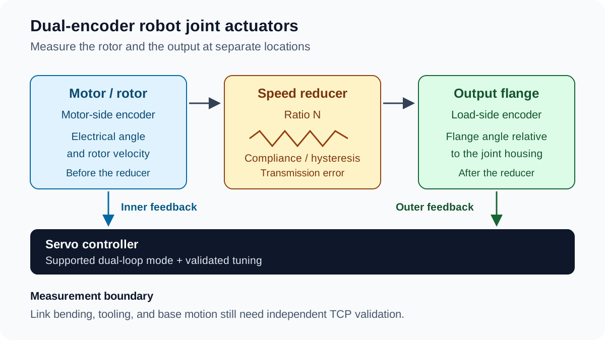
Dual-Encoder Architecture in Robot Joint Actuators: Resolving Transmission Error, Deflection, and End-Effector Drift
Compare dual-encoder robot joint actuators, accuracy limits, tuning risks, and acceptance tests. Use the RFQ checklist to scope your next supplier quote.
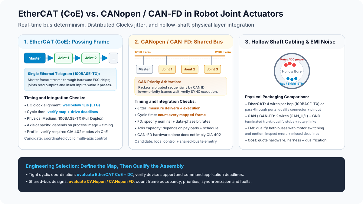
EtherCAT vs. CANopen / CAN-FD in Robot Joint Actuators: Real-Time Bus Jitter, Cycle Times, Daisy-Chain Cabling, and CiA 402 Integration (2026)
Compare EtherCAT vs CANopen and CAN-FD for robot joint actuators: cycle-time sizing, jitter, cabling and CiA 402. Use the checklist to prepare your supplier RFQ.

TCO Analysis for Robot Joint Actuators: Hidden Costs Beyond the BOM
Use this 2026 robot joint actuator TCO guide to price integration, tuning, yield, warranty, downtime, spares, and supplier risk before issuing an RFQ.