
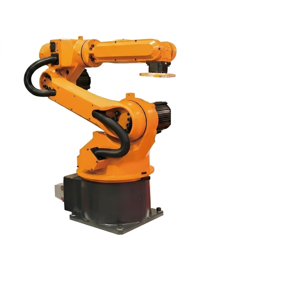
Thermal Derating in IP67 Sealed Robot Joint Actuators: What Datasheets Hide (2026)
Engineering guide to thermal derating in sealed robot joint actuators: IP67 torque loss, supplier datasheet checks, RFQ questions, and test limits.
Key Takeaways
- The Sealing Penalty: Moving a robot joint actuator from an open-air IP20 environment to a sealed IP67 enclosure can reduce its true continuous torque capacity by 30% to 50% due to trapped heat.
- Datasheet Illusions: Most supplier datasheets publish continuous torque ratings based on 20°C to 25°C ambient air with an assumed massive aluminum heatsink. These numbers are invalid for enclosed robotic joints.
- The Motor Constant ($K_m$): When evaluating suppliers for sealed applications, prioritize the motor constant ($K_m$) over peak torque. Higher $K_m$ means less heat generated per Nm of torque.
- Procurement Mandate: Never accept an RFQ quote for a sealed actuator without a temperature-contextualized derating curve from the supplier.
The Hidden Crisis in Robot Joint Sourcing
For procurement teams and engineering managers designing outdoor agricultural robots, cleaning robots, or high-end humanoids, IP67 and IP68 sealing is a mandatory requirement. The logic is simple: keep the water, dust, and debris out to ensure reliability.
However, solving the ingress problem creates a severe thermal problem. A robot joint actuator is fundamentally a high-density heat generator. Inside an actuator, copper windings generate $I^2R$ losses (Joule heating), the stator core generates iron losses (eddy currents and hysteresis), and the gear reducer generates mechanical friction losses.
In a standard open-air environment, convection cooling pulls this heat away. But in an IP67 sealed joint, there is no airflow. The heat is trapped inside the housing. As internal temperatures rise, the actuator hits its thermal limits—either the magnet Curie temperature, which causes demagnetization, or the winding insulation limit, which causes catastrophic electrical shorts.
To prevent this, the actuator's control system must implement thermal throttling, intentionally reducing the available current to lower the temperature. The result? That "100 Nm continuous" actuator you bought can only output 50 Nm after 20 minutes of operation.
This guide provides the framework for buyers and engineers to evaluate, specify, and source IP67/IP68 robot joint actuators without falling victim to datasheet illusions.
Scope, Date, and Limits for This Guide
This 2026 guide is written for global OEM procurement teams and application engineers comparing sealed robot joint actuators for humanoids, cobots, service robots, agricultural robots, and outdoor inspection platforms.
Use it when the joint is passively cooled, IP67/IP68 sealed, and expected to hold repeated RMS torque in 30°C to 55°C ambient conditions. Do not use the sample numbers as a universal derating curve: liquid-cooled joints, oil-filled gearboxes, very large aluminum castings, or short intermittent duty cycles need a supplier-specific thermal model and bench validation.
Before sending an RFQ, pair this article with our Robot Joint Actuator RFQ Template so thermal test conditions, ambient temperature, mounting plate, and duty cycle are requested in writing.
The Physics of Thermal Derating
Understanding why datasheets fail you requires a brief look at the physics of a robot joint actuator.
The continuous torque ($\tau_c$) of an actuator is not a mechanical limit; it is a thermal limit. It is defined as the maximum torque the actuator can produce indefinitely without the internal winding temperature exceeding its maximum rated limit (typically 120°C to 155°C, depending on the insulation class).
Where Heat Comes From
- Copper Losses ($I^2R$): This is the primary heat source during high-torque, low-speed operations. Heat generation is proportional to the square of the current. Therefore, doubling the torque requires quadrupling the heat dissipation capability.
- Core Losses (Iron Losses): This consists of hysteresis and eddy currents. These losses scale with the motor's speed. In high-speed joint movements, core losses become the dominant thermal issue.
- Mechanical Friction: The gear reducer (Harmonic, Cycloidal, or Planetary) generates heat through friction. Harmonic drives, while offering zero backlash, have sliding friction in the wave generator that converts mechanical energy directly into heat.
The IP67 Heat Trap
When a manufacturer tests an actuator to define its "continuous torque" for the catalog, they typically mount it to a large, thick aluminum plate (a heat sink) in a 25°C climate-controlled laboratory.
When you integrate that same actuator into a sealed robotic arm, covered by a cosmetic plastic shell or a sealed aluminum housing, the thermal resistance from the motor windings to the ambient air increases dramatically.
The heat must conduct from the stator windings -> to the stator core -> to the actuator housing -> through an air gap (or thermal pad) -> to the robot's outer shell -> and finally convect to the outside air. Every step introduces thermal resistance (R_th). Because R_th is higher, the maximum allowable continuous current—and therefore continuous torque—must be lowered. This is thermal derating.
The Datasheet Reality Check: IP20 vs. IP67
To illustrate the severity of this issue, let's look at a realistic comparison of the exact same actuator core used in two different environments.
The sample uses a simple steady-state screen: allowable heat is approximately (T_winding limit - T_ambient) / R_th. Replace every value with your supplier's measured winding limit, ambient profile, mounting fixture, housing material, and duty-cycle RMS torque before committing to a BOM.
| Specification Parameter | Open-Air Lab Test (Datasheet) | IP67 Sealed Robot Enclosure (Reality) | Impact on Performance |
|---|---|---|---|
| Ambient Environment | 25°C, free convection | 40°C internal enclosure temp, no airflow | Baseline starting temp is 15°C higher. |
| Mounting Condition | 300x300x20mm Aluminum Plate | Carbon fiber or thin-wall aluminum limb | Loss of the primary conductive heat sink. |
| Thermal Resistance (R_th) | 0.8 °C/W | 2.4 °C/W | Actuator heats up 3x faster per watt of loss. |
| Max Continuous Winding Temp | 120°C | 120°C | Hard physical limit remains unchanged. |
| Allowable Power Dissipation | 118 Watts | 33 Watts | The actuator can only shed 28% of the heat it could in the lab. |
| Effective Continuous Torque | 100 Nm | 53 Nm | A ~47% reduction in usable continuous torque. |
The Procurement Lesson: If your engineering team sizes the joint based on the 100 Nm datasheet value, the robot will fail in the field. When buying for sealed applications, you must derate the supplier's catalog numbers.
Evaluating Actuator Designs for Heat Dissipation
Not all sealed actuators are created equal. When evaluating robot joint modules, look for these specific engineering design choices that superior manufacturers use to mitigate thermal derating.
1. High Motor Constant ($K_m$)
The motor constant (K_m) is measured in Nm/sqrt(W). It represents the torque produced per square root of watt of resistive power loss. It is the purest measure of a motor's thermal efficiency. An actuator with a higher K_m will produce the same torque while generating less heat. When comparing two suppliers with similar dimensions and weights, the one with the higher K_m is vastly superior for sealed applications.
2. Direct Stator-to-Housing Potting
In cheaper actuators, there is an air gap between the motor stator and the outer housing. Air is a terrible thermal conductor. Premium sealed actuators use specialized thermal potting compounds (epoxy or silicone-based) to fill this gap, creating a direct thermal bridge from the copper windings to the external aluminum shell.
3. High-Temperature Neodymium Magnets
Many standard neodymium magnet grades are not intended for sustained high winding-adjacent temperatures. High-end actuators utilize SH, UH, or EH grade neodymium magnets that can tolerate higher operating temperatures without permanent flux loss, providing a much wider thermal margin before catastrophic failure.
4. Integrated Dual Thermal Sensors
Relying on a single thermistor on the control board is insufficient. The temperature at the PCB is vastly different from the temperature deep inside the copper windings. Professional-grade joint actuators embed a PT1000 or NTC thermistor directly into the stator windings, plus a secondary sensor on the drive electronics, allowing the master controller to accurately predict thermal limits and throttle gracefully.
Visualizing the Heat Path in a Sealed Joint
The IP67 Actuator Procurement Checklist
To protect your project from late-stage thermal failures, use this specific checklist during your RFQ and supplier evaluation phase. Do not accept quotes from suppliers who cannot provide verifiable data for these points.
- Request Derating Curves: Have you received a Continuous Torque vs. Ambient Temperature chart, rather than a single torque number?
- Verify Test Conditions: Does the supplier explicitly state the mounting condition (e.g., free air, mounted to aluminum block) used to achieve the published continuous torque?
- Compare Motor Constants (K_m): Have you calculated and compared the K_m (Nm/sqrt(W)) across your shortlisted suppliers to identify the most thermally efficient core?
- Check Insulation Class: Is the winding insulation rated for Class F (155°C) or Class H (180°C) rather than standard Class B (130°C)?
- Confirm Magnet Grade: Has the supplier verified the use of high-temperature neodymium magnets (SH, UH, or EH grade) to prevent demagnetization under heavy duty cycles?
- Assess Potting Strategy: Does the actuator use thermal potting to bridge the air gap between the motor stator and the external aluminum housing?
- Review Sensor Placement: Does the actuator feature direct winding temperature sensors (e.g., PT1000 embedded in copper) rather than just a PCB-mounted thermistor?
Frequently Asked Questions (FAQ)
Q: Can I just buy an actuator with double the continuous torque to compensate for the IP67 derating? A: You can, but it is an inefficient and costly strategy. Oversizing the actuator significantly increases the mass and inertia of the robot joint. For a multi-axis arm or legged robot, adding mass to distal joints requires the proximal joints to be even larger, creating a cascading weight problem. It is much better to select a thermally optimized, high-$K_m$ actuator.
Q: Does liquid cooling solve this problem? A: Yes. Liquid cooling completely changes the thermal resistance equation and can materially increase continuous torque capacity. However, liquid cooling adds immense complexity to the robot system (pumps, radiators, leak risks) and is generally reserved for ultra-high-end industrial or humanoid applications. For most mobile robots, optimizing passive thermal design is the preferred path.
Q: Our robot only uses high torque for 5-second bursts. Do I need to worry about continuous torque thermal derating? A: Yes, due to thermal accumulation. While a 5-second burst is technically "peak torque," if you repeat that burst every 10 seconds, the average power dissipation will rapidly heat up the sealed enclosure. You must calculate the Root Mean Square (RMS) torque of your specific duty cycle and ensure it falls below the derated continuous torque limit of the actuator.
Q: Why don't suppliers just publish IP67 derated numbers in their standard catalog? A: Because marketing. If Supplier A publishes honest IP67 derated numbers (e.g., 50 Nm) and Supplier B publishes open-air numbers (e.g., 100 Nm) for the exact same size motor, uninformed buyers will always choose Supplier B. It is up to the procurement and engineering teams to normalize the data.
Next Steps for Your Project
Understanding thermal derating is the difference between a prototype that works in the lab and a product that survives in the field. Before you finalize your actuator selection, ensure you have modeled your specific duty cycle against realistic environmental constraints.
If you are currently evaluating IP67 or fully sealed actuators for your robotic platform, we can help you bypass the datasheet marketing.
- Review our Robot Joint Actuator Selection Guide for broader architectural decisions.
- Evaluate our line of thermally-optimized Integrated Harmonic Joint Actuators.
- For direct technical alignment on thermal modeling and RFQs, visit our Contact / RFQ page.
Sources and References
- IEC 60529: Degrees of protection provided by enclosures (IP Code) - Official IEC standard page for IP enclosure protection definitions.
- Thermal Recovery of Multi-Limbed Robots with Electric Actuators - IEEE Robotics and Automation Letters / arXiv paper using a data-driven actuator thermal model validated on NASA Valkyrie hardware.
- Estimation and Control of Motor Core Temperature with Online Learning of Thermal Model Parameters - IEEE Robotics and Automation Letters / arXiv paper on motor core temperature estimation and control for continuous humanoid movement.
- Alternating Current Motors in Detail - NEMA training document covering motor construction, winding insulation classes, temperature rise, and heat effects on motor life.
Author

Categories
More Posts
Functional Safety (SIL 3 / PL e) in Robot Joint Actuators: A 2026 Guide
Use this 2026 guide to evaluate SIL 3 / PL e robot joint actuators, STO/FSoE requirements, procurement checks, and RFQ questions for global cobot OEMs.
Hollow Shaft vs Solid Shaft Robot Joint Actuators: A Procurement and Engineering Guide
An in-depth analysis of hollow vs. solid shaft robot joint actuators. Learn how internal cable routing impacts torque density, sealing, cost, and procurement strategy.
Robot Joint Actuator Selection Guide for OEM Buyers (2026)
A practical selection framework covering reducer type comparison, torque-speed reality checks, backlash/stiffness targets, thermal margins, and RFQ-ready data for robot joint actuator programs.